ONYX - 9.0 - Utilisation - Partie Dynamique de ONYX Designer/en
Différence entre versions
(Page créée avec « '''In short:''' ») |
(Page créée avec « *The selection zone of the data block is configured by creating a ''Group:'' ») |
||
| Ligne 358 : | Ligne 358 : | ||
'''In short:''' | '''In short:''' | ||
| − | * | + | *The selection zone of the data block is configured by creating a ''Group:'' |
[[File:onyxdesigner-image55.png]] | [[File:onyxdesigner-image55.png]] | ||
Version du 26 juillet 2019 à 08:40
Sommaire
Dynamic Part (Map Tab)
Definition
The Map part of a project corresponds to the dynamic part of designs that are made according to the datastreams processed by the template. The main elements which can be placed in this part are data files printable information.
To design this part, select the "Map F" tab (and "Map B" for the duplex of the document). In this view, elements of the "Draw" part are displayed as watermarks so that positioning the data to be printed is easier.
" Spooled File"
To retrieve and identify data to be printed, designing a Designer project is done using an example file. This example file is an image of the production spooled file to format.
Designer supports two types of data files in native mode: paginated text files and XML files in Mapping format. Input file types are configured in the project properties.
Designer processes files with .PAG or .TXT extensions. Text files usually have a ".PAG" extension because they need to be paginated. Text files can be paginated by running the "MAPPAGIFS" command in Onyx Server where an argument specifying the number of lines per page ("Overflow") will be given.
XML files need to respect a particular syntax so that the application can properly process them. (see 6.3 XML Mode: syntax and specifications).
To open and display an example file in DESIGNER, the spooled file view needs to be activated in the Display Menu:

In the "Home" tab, click on ![]() and select the file you want to load in the application.
and select the file you want to load in the application.
The spooled file view then displays the data from the spooled file to format.

![]()
To help you design your project, you can preview the result without having to print the document. To do so, click on the Preview button in the Home menu.
XML: syntax and specifications
In XML mode, the design principles are the same and are put in application using an example file loaded in the application.
As stated in 4.2. Creating a project, to load a .xml document, it is important not to forget to go to the project Properties and check that in Parameters > Mode = XML.

The Spooled file view is then called the XML view and displays the content of the file in a tree view.

Data structure
XML files that are processed by Designer in native mode have to respect a specific pattern and syntax, such as:
<page name="..."> … </page> tags mark out the pages of the document. In the last example, there is only one page.
- <field name="...">value1</field> tags correspond to unit-based information (the equivalent of ‘zones’/'fields' in Designer).
- <group name="..."> … </group> tags refer to a particular number of lines which contain zones, such as a ‘group’ in Designer.
- <line name="…"> … <line> tags correspond to the lines inside of these groups.
If we were to use this structure with a paper invoice:
- <page name="..."> … </page> corresponds to the pages of the invoice.
- <group name="..."> … </group> marks out the body of the invoice (from the first line to the last).
- <line name="…"> … <line> describes every line in the body of the invoice.
- <field name="...">value1</field> can correspond to two things:
- If this tag is on the outside of a group, it corresponds to unit-based information in the invoice. In which case, value1 corresponds to the invoice number in the header, for instance, or to the client number, the type of invoice, etc.
- If this tag is inside a group, value1 corresponds to the value of the zone in the line. For instance, the product code, its name, price, etc.
XML pattern specifications
The specifications needed for Designer to process the file are the following:
The XML header needs to specify the file encoding.
Example : <?xml version="1.0" encoding="UTF-16" standalone="yes" ?>
The root tag of XML data needs to be called doc.
All tags mentioned hereafter need to have at least one attribute named name. Information will be identified, retrieved and formatted by the application via the use of this attribute.
The tags and attributes names are case-sensitive and need to be written in lowercase letters.
For the application to access it, data must be placed in pages in between the <page name="…"> and </page> tags. One document can contain several pages.
Inside a page, data is organised per unit-based fields (balise <field name="…">) or per information groups (balise <group name="…">).
Information groups are composed of lines (balise <line name="…">).
The lines contain unit-based informations (balise <field name="…">).
Here is an example of an XML file:

XML data can be placed on the outside of a page as information linked to the overall document and not to the page in particular. However this data will not be accessible to Designer and thus cannot be processed to design the document. Nonetheless, this data can be used in the M-Processing Server engine.
XML view in Designer

An XML example file is loaded in DESIGNER in the same way that is use to load a text file. In the XML view, data is displayed as a list of elements.
Page break on an XML field value
In the Proprieties of a group, the page break generation can now trigger on the change in XML field value.
Par example:
<group name="groupe">
<line name="ligne">
<field name="id">1</field>
<field name="data"> data </field>
</line>
<line name="ligne">
<field name="id">1</field>
<field name="data"> data </field>
</line>
<line name="ligne">
<field name="id">2</field>
<field name="data"> data </field>
</line>
<line name="ligne">
<field name="id">2</field>
<field name="data"> data </field>
</line>
…
</group>
In this example, if the field used to generate a page break is the field "id" then the page break will be generated after the execution of the second line.
There are several options in the interface for the Page break parameter:


- None: the group does not generate any page break.
- Limit: the group triggers a page break on a positioning limit.
- XML Field: the group triggers a page break on a XML field value change.
- Limit and XML Field: the group triggers a page break on a positioning limit and on a XML field value change.
When generating automatic page breaks, managing the recovery of headers is possible with the options "Header" and "Last header":

- Header: to choose the name of the line of the XML file which acts as header.
- Last header: if checked, only the last header is kept. The box is checked by default.
When generating a page break, the last header (or all of the above headings, if the option is unchecked) is used at the start of the new page.
In the XML, if two header lines follow each other, they are considered as one single header.
If a page break is triggered just after a header line, it is not printed and is carried over to the next page.
Edit a variable list of items as a table
To display a list of items in an XML group as a table, the script tool must be used.
The rowtotable feature rearranges the lines of a group so as to obtain a horizontal distribution of the elements.
Syntax:rowtotable(name of the group, maximal number of columns in the table);
The rowtotable feature has two settings:
- Name of the group: contains the name of the group to be reorganized in a table, surrounded by double quotes.
- Maximal number of columns in the table: Maximal number of columns in the table.
Note: All the lines of a group should have the same name.
For example:
<group name="invoice">
<line name="item">
<field name="name">item 1</field>
</line>
<line name="item">
<field name="name">item 2</field>
</line>
<line name="item">
<field name="name">item 3</field>
</line>
<line name="item">
<field name="name">item 4</field>
</line>
<line name="item">
<field name="name">item 5</field>
</line>
<line name="item">
<field name="name">item 6</field>
</line>
<line name="item">
<field name="name">item 7</field>
</line>
<line name="item">
<field name="name">item 8</field>
</line>
</group>
To rearrange this group as a three-column table, use the following script:
rowtotable("invoice",3);
This script will effectively change the group which then becomes:
<group name="invoice">
<line name="item">
<field name="name_1">item 1</field>
<field name="name_2">item 2</field>
<field name="name_3">item 3</field>
</line>
<line name="item">
<field name="name_1">item 4</field>
<field name="name_2">item 5</field>
<field name="name_3">item 6</field>
</line>
<line name="item">
<field name="name_1">item 7</field>
<field name="name_2">item 8</field>
</line>
</group>
Dynamic elements
This part of the documentation presents the basic elements that can be added in the dynamic part of a project in order to get started with the main features of the application.
Zone
Definition
A zone is the main element, which allows you to retrieve information in the input data in order to position and format them in the final graphical document.
In text mode, the information is identified by the following three elements of data:
- a row number,
- a column number,
- a length.
In XML mode, it is identified by the name of the XML field (field tag).
A zone can only read one row at a time.
It is represented in the following two ways in the designing space:
- The zone is empty, no data is associated with it: an icon appears in its upper right corner.
![]()
- The zone is associated with an element of data, it appears without an icon.
![]()
A zone is identified by its name, defined in the properties window (see a.2 Creating a zone for more details).
Creating a zone
There are two methods you can use to create a zone:
Select the corresponding icon and its type in the Data tab and hold the button of your mouse down where you want the element to be placed. This method creates an empty zone. To link the zone to an element of data from the source file, select the data in the spooled file view (see the second method below) then, drag and drop it in the zone which was created previously, by holding down the Ctrl key.

Select the data to be recovered in the Spooled file view then, drag and drop it where you want, in the designing space to create a zone automatically linked to the data you selected.

Once the zone has been created, select it and display the 'Properties view to fill in the following information:

Name :
Name (of the zone): this information is used as internal information in Designer, it identifies the different objets in the project. When creating an empty zone, this field is also empty and equals to the value of the data as the zone is created from the Spooled file view.
Text printed before/after: to add text before and/or after the retrieved information.
Position :
Position of the information in the data spooled file: column, length, beginning line.
This is also used to extract a certain quantity of information in XML mode.
Position in the document:
to change the position of the zone on the page.
Data Type:
defines how the Designer application processes the information retrieved (see a.3 Types of zones).
Font:
To set all formatting options: font, size, colour, framing, orientation, etc.
Types of zones
The Designer application offers various processing options according to the type of data to process:
- Text: prints plain text.
- Normal: copies the values located in the positions defined by the zone whether they are letters, numbers or blanks.
- Optimized: copies the characters located in these positions except for blanks at the beginning and end of these positions. The framing to the left or to the right is always observed. There is no shift due to blanks in the spool.
- Substitution: used to replace a value of the spool by another one stored in a file called replacevalue.txt. By default, this file is in its blank state in the Designer installation folder. To carry out the substitutions, place it in the lgobitmap folder. The folder needs to contain the values to be replace followed by replacement values and separated by a tab. This sub-type is explained in further detail in 8.3. Replacing characters.
- Translate: substitutes a value for its translation in another language. A zone type Tools / Set Lang is used beforehand to define the file with the translated values. The program searches for the corresponding input in the translation file for each Texte / Translate zone which is defined in the template. The file must be placed in the lgobitmap folder and its name must start with "Translate_".
- Compressed: zone displaying the recovered text into the dedicated space. The text occupies the width of the zone and adjusts the font size between a maximum and a minimum so that the text covers all the dedicated space.. If the minimum font size does not display the entire text, it is truncated and followed by "…".
- Truncated: zone displaying the recovered text into the space allowed by the zone width. If the text cannot be fully displayed, it is truncated followed by "...".
- Barcode: encodes and prints barcodes. The list of available barcodes can be seen in 8.1 Barcodes
- Tools: inserts a page number, images, … but also display the total number of pages, pages in the current batch, …
- Page Number: numbers each edited page. The page number is not necessarily the same as that in the original spooled file. If M-Processing Server is set to exclude certain pages, the number of edited pages will not necessarily be the same as the number of pages in the original spooled file.
- Batch Number: displays the batch number.
- Page Number (Batch): displays the page number in the batch.
- Total Number of Pages: displays the number of pages in the document.
- Total Number of Batches: displays the number of batches in the document.
- Total Number of Pages (Batch): displays the number of pages in the current batch.
- Specific replacement: replaces a value in the spooled file processed by another value which was retrieved in a file. For example, the customer number displayed in the spooled file can be replaced with the customer's name which is retrieved in a database file.
- Image: prints out a different image depending on the value of the spooled file.
- Export: this type of zone allows you to retrieve information from the spooled file and export it to a physical file.
- Repl. File: retrieves text in a file. The name of the zone must correspond to the name of the file. The file must be in the lgobitmap folder and be called data_NAMEOFTHEZONE.txt (where NAMEOFTHEZONE is the real name of the zone). The row and length settings of the zone indicate the row and length of the text to be retrieved.
- Input Text: creates interactive input fields to design SOAP forms in PDF or HTML format. As the user opens the form generated in Adobe Reader or a web browser, he can fill in input fields and send data to an M-Processing Server URL in a Web entry point by clicking on the SUBMIT button, which is actually a Tools / Input Text zone called SUBMIT (system name).
- HyperLink: adds a URL link.
- Set Lang: to specify the file which contains the translations. The latter must be in the lgobitmap folder and its name must start with Translate_. This zone is not printed in the final document, it cannot be seen for preview nor mapping. The name of this zone is not really important, however it must be declared before any other Designer zone that requires translation. Then, the program searches for the corresponding input in the translation file for each Texte / Translate zone defined in the template.
- XPS Message: Inserts an XPS file in the current page. This zone is a link to an XPS file which is on the M-Processing Server. This file must only contain one page and must also be placed in the lgobitmap folder (directly or in a sub-folder). It is not case sensitive. If changes are made to the XPS file, it will impact the projects that use it.
- XPS File: unlike XPS Messages, the files inserted with XPS File zones:
- can contain several pages.
- are whole pages.
- create additional pages in the output file.
- Metadata: indexes the document for archiving (non printed data). The length of the metadata is unlimited.
- Index: index zone by default, used in XPS manipulations and in M-Storage Manager as criterion.
- MapFrom: index reserved to send emails. The value range for this area will be used to set the email sender..
- MapSend: index reserved to send emails. The value range for this area will be used to define the address of the recipient.
- MapCopy: index reserved to send emails. The value range for this area will be used to set the copy recipient.
- MapBCopy: index reserved to send emails. The value range for this area will be used to define the recipient in hidden copy.
- MapNote: index reserved to send emails. The value range for this area will be used to define the body of the email.
- MapSubject: index reserved to send emails. The value range for this area will be used to define the mail subject.
- MapOrg: index reserved to send faxes. The value range for this area will be used to identify the sender.
- MapTo: index reserved to send faxes. The value shown by this area will be used to define the recipient.
- MapUser: index reserved to send faxes. The value range for this area will be used to identify the owner.
- MapFormat: index reserved to send faxes. The value range for this area will be used to define the document format (.BMP, .JPG, .EXE, .PAG, .PDF, .TIF, .TIF_FAX, .TXT, .XLS).
- Memory: insert and store information (not printed) which will later be recovered and used in the template. (see 8.1.b. Combined data)
- Text: save alphanumeric information and delete the spaces after the text.
- Text with spaces: save alphanumeric information and keep the spaces after the text.
- Integer: save integer-type digital information.
- Float: save floating-type digital information.
- SQL: save alphanumeric information found in a database using an SQL query.
- Protect SQL: save alphanumeric information found in a database using a protected SQL query.
- Math. calculation: use memory zones to perform a calculation.
- Memory Replacement: retrieve information saved in the memory zone.
- Memory Translate: save alphanumeric information resulting from the automatic translation of the information retrieved in the spooled file.
- Graph: used to generate a graph using multiple elements of data
- Graph data.
- X-axis data.
- Y-axis data.
- Graph title.
- X-axis title.
- Y-axis title.
- Legend data.
- Minimum value of the Y-axis.
- Maximum value of the Y-axis.
- No. of intervals of the Y-axis.
- Rounding to the nearest n of the Y-axis.
- Origin of the Y-axis.
The construction of a graph is detailed in section 8.6. Drawing a graph.
Designer can automatically convert old graphs types in complex graphics. This feature facilitates the conversion of old projects in XPS projects.
- Conversion: converts numerical data according to conversion rules (Euro to Dollar for example) defined in Onyx Server > Managing Designer Formats > Managing Rates (01=E1 ; 02=E2 ; …)
- XPS PrintTicket:
- Copy: number of copies to print.
- Input Bin: input bin number (printer paper feed).
- Output Bin: output bin number.
- Media Type: Type of paper (A4, A5, etc...).
- Force Front Side: determines the mode Single / Duplex when printing.
- Commands: adds data in the print stream, in printer language. As for the project properties, Document and Page (see 4.2. Creating a project), a "Commands" zone defines the printer language data for the following languages: PCL5, APFDS, PDF, ZPL, DPL, TEC, IGP, IPL and EPL. A zone can contain data for several different languages. When converting the XPS to the output language, the corresponding data to the output language will be used.
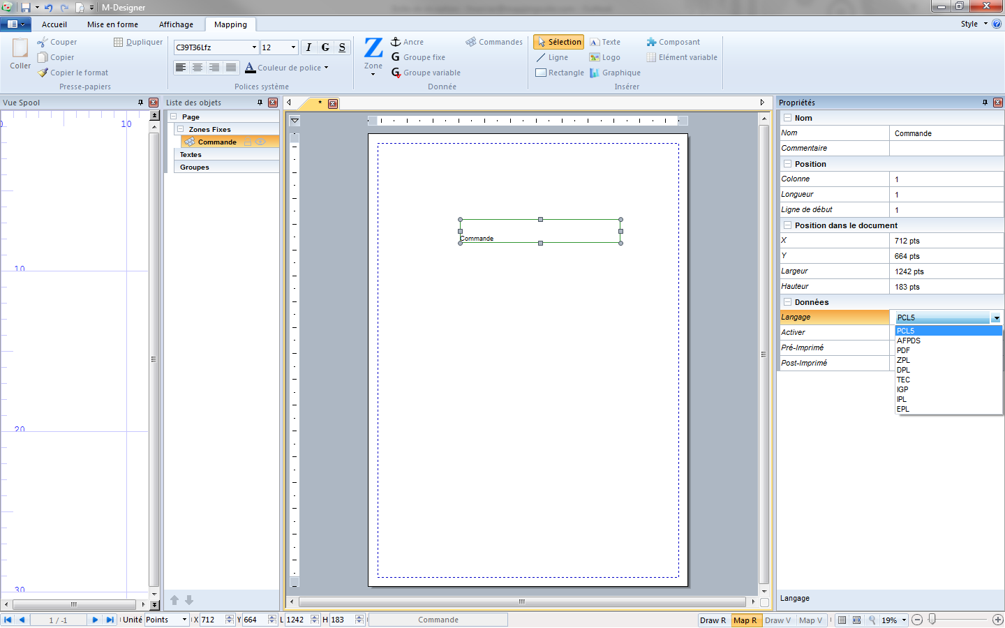
Language: select language.
Activate: enable zone for the selected language.
Pre- and Post-Printing: Data written before and after the retrieved data from the spooled file.

Writing hexadecimal data in the "pre-" and "post-printing" can be done using the following syntax: \x followed by the hexadecimal value of two characters.
Groups
Definition
A group can be used to retrieve several rows of a spooled file. It is defined by a beginning row and an end row. It is shown in red in the designing space:

A group can be fixed (fixed beginning and end rows) or variable (variable beginning and end rows).
Creating a fixed group
The creation of a fixed group, is similar to the creation of a zone.
- Create an empty group from the Ribbon menu, select the data of the source file, drag and drop it in the group you created beforehand while holding down the Ctrl key.


- Select data in the Spooled File view, use the drag and drop method to place it in the designing space to create a group automatically which is linked to the zone you selected in the spooled file.
Once the group is created, its informations must be specified in the Properties view:

Name:
- Name (of the group): this information is used as internal information in Designer, it identifies the different objets in the project. When creating an empty zone, this field is also empty and equals to the value of the first selected line of data as the zone is created from the Spooled file view.
- Position in the document:
- Used to change the position of the group on the page.
- Position:
- Identifies the beginning and end rows in the block of information to recover.
- Offset: print position of the first row in relation to the group
- Option:
- Exclusive conditions: For one row of the group, a true condition will be performed exclusively without testing the following rows
- Table: allows zones of a group to behave like the cells of a table. Zones of the same line find themselves automatically pressed against each other. Resizing or moving a zone impacts the size and the position of the adjacent zones. In addition, the group's lines (or conditions) are visually represented in the design window. The zones are vertically distributed according to their line. This option is detailed in 8.5.b. Drawing a dynamic table.
- Variable:
- Used to change the type of group: from fixed (the beginning and end rows are static) to variable (the beginning and end rows are variable and defined by conditions).
If the user requests a preview, no information will be printed. Indeed, a group only defines the limits between which the data is to be retrieved from the spooled file.
Given that the limits of the data selection zone are defined using the Beginning line and End Line fields of the group, the data must then be retrieved by creating one or more Zones inside the group.
In short:
- The selection zone of the data block is configured by creating a Group:
- On récupère les données à l'intérieur de ce bloc de données par la création d'une Zone :

- Nous pouvons alors constater que toutes les lignes de notre bloc de données sont récupérées grâce à l'aperçu (Ctrl+w). Il est possible de créer plusieurs Zones issues du bloc de données, de les placer dans le groupe et de conditionner leur mise en page (voir 6.4.c. Une condition).

Creating a variable group
Le principe du groupe variable est identique au groupe fixe c’est-à-dire qu’il permet de récupérer plusieurs lignes d’information dans le spool. Lorsque la ligne de début ou la ligne de fin du groupe n'est pas toujours au même endroit dans le spool ou que vous voulez que les informations ne soient pas toujours imprimées au même endroit dans la page, vous devez alors utiliser un groupe variable.
Un groupe variable utilise une condition de début et une condition de fin. Le groupe commence à s'exécuter quand une condition est validée et il s'arrête lorsqu'une autre condition est validée ou lorsqu'il a exécuté un certain nombre de lignes. Un groupe variable peut-être exécuté une ou plusieurs fois dans la page.
De plus, la position des valeurs imprimées par un groupe variable peut être variable.
Vous pouvez définir, par exemple, que les valeurs imprimées par un groupe se positionnent après les valeurs imprimées par un autre groupe. Nous parlerons alors de positionnement relatif.
Vous pouvez aussi définir que le total de la facture s'imprime toujours un centimètre après la dernière ligne de produits (qu'il y ait 5 ou 20 lignes). La position du total facture changera donc en fonction du nombre de lignes de produits que contient cette facture.
Un groupe peut être variable en :
- taille : les lignes de début et de fin sont déterminées dynamiquement par conditions.
- position d’impression : les groupes variables peuvent être chainés les uns à la suite des autres, le groupe n+1 commençant à s’imprimer dès que le groupe n est terminé.
Ces deux types de variable peuvent exister de façon distincte ou conjointe.
Pour créer un groupe variable, il suffit de cliquer sur l’icône ![]() puis de dessiner le groupe sur l’espace de conception.
puis de dessiner le groupe sur l’espace de conception.
La vue Propriétés s’affiche pour renseigner les informations du groupe :

- Nom :
- Nom (du groupe) : information interne à Designer, permettant d’identifier les différents objets dans le projet. Ce champ est vide lors d'une création d'un groupe à vide.
- Position dans le document :
- Permet de modifier le positionnement du groupe dans la page.
- Position :
- Décalage : position d’impression de la première ligne par rapport au groupe.
- Option :
- Conditions exclusives : pour une ligne du groupe, une condition vraie s’exécutera de manière exclusive sans tester les suivantes.
- Répéter : si la condition de début apparaît plusieurs fois, le groupe s'exécutera plusieurs fois à condition que la condition de fin ait été validée entre temps.
- MapOffice : permet de vérifier la conception d’un groupe MapOffice (voir la documentation Connect pour la conception d’un document Office).
- Tableau : permet aux zones du groupe de se comporter comme les cellules d’un tableau. Les zones d’une même ligne se retrouvent donc automatiquement collées. Redimensionner ou déplacer une zone impacte la taille te le positionnement des zones adjacentes. De plus, les lignes du groupe (ou conditions) sont visuellement représentées dans la fenêtre de conception. Les zones sont, quant à elles, réparties verticalement en fonction de leur ligne.
- Variable :
- Permet de changer le type de groupe : de fixe (les lignes de début et de fin sont statiques) à variable (les lignes de début et de fin sont variables et définies par des conditions).
- Espacement : Espacement avant l'impression du groupe.
- Type de condition d'arrêt : Permet de conditionner la fin de l'exécution du groupe variable.
- Groupe précédent : Indique après quel groupe fixe le groupe variable s'exécute.
Conditions
Condition d'Exécution
Les conditions d'exécution permettent d'exécuter, ou non, l'objet conditionné en fonction d'une valeur dans le spool.
Une condition peut s’appliquer à la fois sur une page, un composant, un groupe, une zone, une ligne ou un rectangle.
Si la condition est validée alors l'objet est exécuté. Dans le cas contraire, aucune autre action n'est réalisée. Pour réaliser deux actions différentes en fonction de la présence ou non d'une valeur de spool, il vous faut donc créer deux objets.
Exemple : Vous voulez écrire différemment en noir quand il y a la valeur Facture et en rouge quand il y a la valeur Avoir dans une ligne de spool. Vous créez alors une zone avec une police noire quand il y a Facture, et une zone qui utilise une police rouge quand il y a Avoir car la création d’une seule condition dans une même zone : « police noire si Facture et police rouge si Avoir » n’est pas possible.
Les conditions sont gérées différemment si l'objet est fixe ou s'il appartient à un groupe. En effet, dans un groupe, la condition est nommée et elle est rattachée au groupe. Nous pouvons donc associer plusieurs objets à une même condition sans devoir ressaisir celle-ci à chaque fois.
Condition de début
La condition de début détermine la première ligne d'exécution du groupe variable. Le groupe commence à s'exécuter sur la ligne où la condition de début est vraie.
Onyx Server teste la validité de la condition à partir de la première ligne du spool (ligne 1). Dès que la condition est vérifiée, le groupe commence à s'exécuter. Il s'arrête lorsque la condition de fin est vérifiée à son tour.
Il est également nécessaire de définir au niveau de la condition de début si le groupe est imprimé de manière fixe sur la page ou s'il est imprimé en positionnement relatif par rapport à un autre groupe. Il est aussi possible de choisir que le groupe s'imprime un centimètre après la fin d'un autre groupe.
Si la condition de début de groupe n'est vérifiée sur aucune des lignes du spool, le groupe n'est pas exécuté.
Si la condition de début est vérifiée sur plusieurs lignes du spool, le groupe ne s'exécute qu'une seule fois : à partir de la première ligne où la condition est vérifiée.
Condition de fin
La ligne de fin d'un groupe variable peut être définie de deux manières :
- nombre de lignes d'exécution,
- condition de fin.
En connaissant le nombre de lignes que doit exécuter le groupe variable, Il est alors possible de paramétrer ce nombre en entrée après avoir coché Nombre de lignes.
La condition d'arrêt n'est pas un test de comparaison par rapport à une valeur présente dans le spool mais le nombre de ligne après lesquelles le groupe s'arrête.
La condition de fin détermine la dernière ligne d'exécution du groupe variable. Le groupe arrête de s'exécuter sur la ligne où la condition de fin est vraie. De plus, cette ligne peut être exclue (non exécutée) ou incluse (exécutée).
Condition Exclusive
Dans un groupe, il est possible de gérer plusieurs conditions. Par défaut, il y en a une seule qui est la condition Aucune et qui s'applique pour toutes les nouvelles zones créées.
Exemple :
Dans un groupe contenant des lignes de produit, il peut y avoir des lignes de sous-totaux. Il est possible d’utiliser plusieurs zones pour imprimer ces différents types de ligne (pour mettre les sous-totaux en gras par exemple) grâce à une condition.
Ici, il y a donc, à la base, deux conditions : une condition Sous-total à laquelle est rattachée au moins une zone qui imprime en gras et la condition Aucune à laquelle est rattachée la zone qui écrit en standard pour les lignes de produit.
Si le groupe fonctionne en conditions exclusives, une seule condition est appliquée par ligne, même si plusieurs sont vraies (seule la première créée est appliquée). Les lignes de produit sont imprimées en standard par la zone sous la condition Aucune et les lignes de sous-totaux sont imprimées en gras par la zone sous la condition "Sous-total".
Si le groupe fonctionne en conditions non exclusives, toutes les conditions vérifiées sont appliquées par ligne. Dans ce cas, les lignes de sous-totaux sont imprimées deux fois, une fois en gras par la zone sous la condition Sous-total et une fois en standard par la zone sous la condition Aucune. En effet, la condition Aucune est toujours vraie.
Le fonctionnement en conditions non exclusives est très peu utilisé. Il oblige à ajouter dans les filtres d'une condition les conditions inverses des autres conditions. Dans ce type de fonctionnement, la condition Aucune n'est pas utilisée. Il sert uniquement à répéter l'impression d'une information, ou à imprimer sur deux lignes des informations figurant sur une même ligne de spool.
La condition Aucune ne peut pas être supprimée. Si vous ne souhaitez pas l'utiliser, il faut n'y rattacher aucun objet.
Type de comparaison
Lors du paramétrage des conditions, vous pouvez tester :
L'existence dans la ligne : il y a dans une ligne ou dans toute la page.
L'absence dans la ligne : il n'y a pas dans une ligne ou dans toute la page.
La supériorité stricte (numérique) : >.
L'égalité ou la supériorité (numérique) : =>.
L'infériorité stricte (numérique) : <.
L'égalité ou l'infériorité (numérique) : =<.
Le numéro de la page.
Le numéro de la ligne.
Ces tests permettront à Designer de valider ou pas une condition.