ONYX - 9.0 - Utilisation - Création Projet de ONYX Designer/en
Différence entre versions
| (2 révisions intermédiaires par le même utilisateur non affichées) | |||
| Ligne 16 : | Ligne 16 : | ||
==Creating a project== | ==Creating a project== | ||
| − | [[File: | + | [[File:OX_D_19.PNG]] |
To create a new project, go to the File menu > New > Project. | To create a new project, go to the File menu > New > Project. | ||
| Ligne 24 : | Ligne 24 : | ||
In the ''Display'' tab, we recommend you to check the ''Properties'' box in the ''Show/Hide'' tab, a window on the right part of the screen appears displaying all the properties to define. | In the ''Display'' tab, we recommend you to check the ''Properties'' box in the ''Show/Hide'' tab, a window on the right part of the screen appears displaying all the properties to define. | ||
| − | [[File: | + | [[File:OX_D_20.PNG]] |
First, '''you must''' specify both of these parameters: | First, '''you must''' specify both of these parameters: | ||
| Ligne 35 : | Ligne 35 : | ||
Other properties can be configured in this panel: | Other properties can be configured in this panel: | ||
| − | [[File: | + | [[File:OX_D_21.PNG]] |
*''Description''= user information (limited to 25 characters maximum). | *''Description''= user information (limited to 25 characters maximum). | ||
Version actuelle datée du 29 août 2019 à 11:53
Creating a project
Project
A Designer project is made up of an overlay, which is the static part of the template, and a data file, which is the variable or dynamic part. A project is identified by a specific format name and sequence number which make it unique within the production server..
On a PC Drive or Network share, a project is made up of three files (or five in the case of a double-sided project):
- A .mpw file with the overlay in simplex (another one for the duplex if necessary)
- A .mpi file with the data formatting in simplex (another one for the duplex if necessary)
- A .mpp file identifies the project and associates it with the other .mpw and .mpi files.
The project term is only used as the template is designed in Designer. Once it is generated on the server, we refer to it as a format and a sequence number.
Creating a project
To create a new project, go to the File menu > New > Project.
The designing view then displays the project as a blank page with default parameters (portrait, A4, simplex).
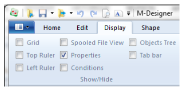
In the Display tab, we recommend you to check the Properties box in the Show/Hide tab, a window on the right part of the screen appears displaying all the properties to define.
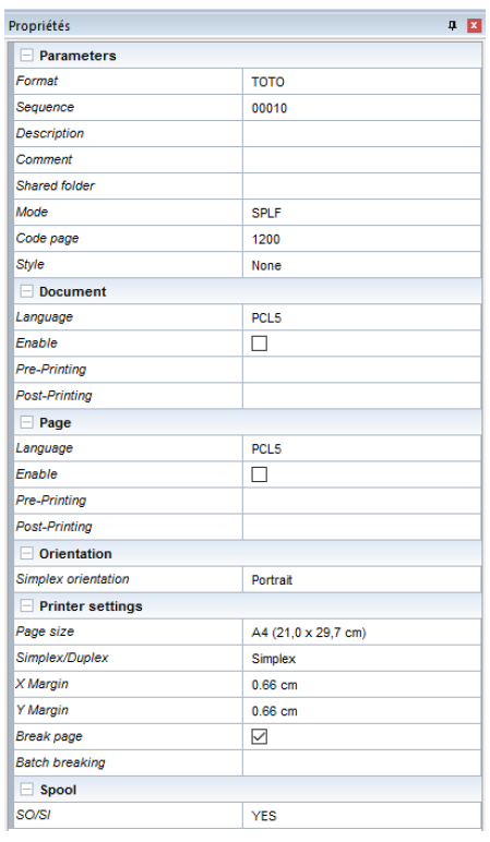
First, you must specify both of these parameters:
- Name of the format = ID of the format with ten characters maximum.
- Sequence = numerical ID of the sequence with five characters maximum.
Formats and Sequences will be explained in further details below.
Other properties can be configured in this panel:
- Description= user information (limited to 25 characters maximum).
- Comment = additional information.
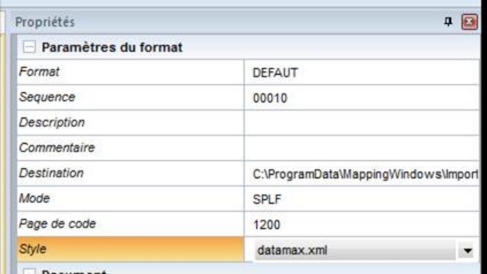
- Destination = generation path of the project (also defined in Preferences).
- Mode = type of data to format: SPLF (text) or XML.
- Code Page = to open a non-Unicode spooled file with an XPS template specifying the file code page in the project properties. This option can only be accessed in SPLF mode.
- Style = selection of the style sheet (also defined in Preferences). This option is explained in further details below.
- Document and Page = allows you to add data in printer language in the output datastream for the following languages: PCL5, APFDS, PDF, ZPL, DPL, TEC, IGP, IPL and EPL. A zone can include data from different languages. When the XPS file is converted to the output language, the data corresponding to the output language is used. Data is specified at the beginning and end of the document.
- Orientation = portrait or landscape fr the simplex and potentially the duplex side.
- Page size (ISO standard formats or customised format) and margins.
- Selection of a simplex or double-sided project (flip the page on the long or the short edge).
- Page break = default setting of the application as it processes data one page at a time and adds a page break once the data of a page has been completely processed. If the break is deactivated, the data of the following page will be placed after that of the page processed.
- Batch breaking = defines a Metadata type zone which will be used to group the pages of the final document together (see 8.8.a. Pagination management by batch breaking).
- Position = if the page break is disabled, this option allows you to specify the position of data on the following page, i.e. to the right of the current page (horizontal shift) or below (vertical shift).
The SO/SI property is used under Windows and Unix to reproduce a native function under iSeries, i.e the EBCDIC spooled file management containing both SBCS and DBCS characters (in particular Asian and Japanese spooled files). This property notifies the application of the detection mode and rendering of the Shift Out and Shift In information (non-printable 0x0F and 0x0E hexadecimal characters) framing the DBCS texts to comply with the spacing between the characters regardless of their width.
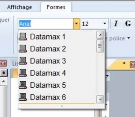
In detail, the Style option both limits the number of fonts which can be used in a template and renames these fonts using an alias. For instance, this simplifies the use of resident fonts in a template by renaming the TTF fonts installed on the workstation with the name of the resident fonts of the target printer.
The generated XPS file embeds the new name of the fonts as defined in the style, these names can therefore be used to define alternative fonts in the conversion profile.
Example of a style to print on a Datamax printer:
<?xml version="1.0" encoding="windows-1252" ?>
<style>
<fonts>
<font name="Arial" alias="Datamax 0"/>
<font name="Arial" alias="Datamax 1"/>
<font name="Arial" alias="Datamax 2"/>
<font name="Arial" alias="Datamax 3"/>
<font name="Arial" alias="Datamax 4"/>
<font name="Arial" alias="Datamax 5"/>
<font name="Arial" alias="Datamax 6"/>
<font name="Arial" alias="Datamax 7 (OCR-A)"/>
<font name="Arial" alias="Datamax 8 (OCR-B)"/>
<font name="Arial" alias="Datamax 9 (Arial)"/>
</fonts>
</style>
Designer comes with the following styles by default: Datamax, Eltron, IGP, Intermec, TEC, and Zebra so that older non-Unicode templates can be re-used.
The selection of these styles is automatic when opening an older template.
The project is now ready to be developed.
Format/Sequence
A Format, viewed in Onyx Server, is the equivalent of a Designer project but once it was generated and imported on the production server. The same format can be composed of several sequences.
Every Sequence is conditioned to run on different pages of a data file (spooled file or XML file).
Here is an example to better understand the benefit of having several sequences for one project:
On an invoice with 3 pages:
- The first page includes the recipient's address, the sender's address as well as the start of the invoice table (Page type 1)
- The last page includes the total of the invoice (Page type 2)
- All the other pages contain the body of the invoice (Page type 3)
Processing the spooled file with the same format is difficult since formatting can differ depending on the page type. Three formats will then be created, one for each page type.
These three formats will have the same name because the three together make THE document "invoice" template, however they will have different sequence numbers:
- Sequence 00010 runs on page type 1.
- Sequence 00020 runs on page type 2.
- Sequence 00030 runs on page type 3.
When running the invoice format on a data file, a MERGE of these sequences is carried out to process the spooled file entirely.


