ONYX - 9.0 - Utilisation - Les principaux menus d'administration/en
Différence entre versions
(Page créée avec « This is the conversion profile to use when sending XPS files. The displayed profile is included in the <label> parameter of the XPSConfig.conf file. If the file to print i... ») |
(Page créée avec « This is the destination address of the printer (or print server). The IP address of the peripheral or its DNS name can be used. This parameter concerns LPR, RAW and IPDS t... ») |
||
| Ligne 740 : | Ligne 740 : | ||
<u>IP address</u> | <u>IP address</u> | ||
| − | + | This is the destination address of the printer (or print server). The IP address of the peripheral or its DNS name can be used. | |
| − | + | This parameter concerns LPR, RAW and IPDS type connections. | |
| − | + | In the case of an EMAIL printer, the IP address of the SMTP server is used. | |
Version du 7 août 2019 à 10:01
Sommaire
- 1 Introduction
- 2 Configuration management
- 3 Managing Robots
- 4 Managing prints
Introduction
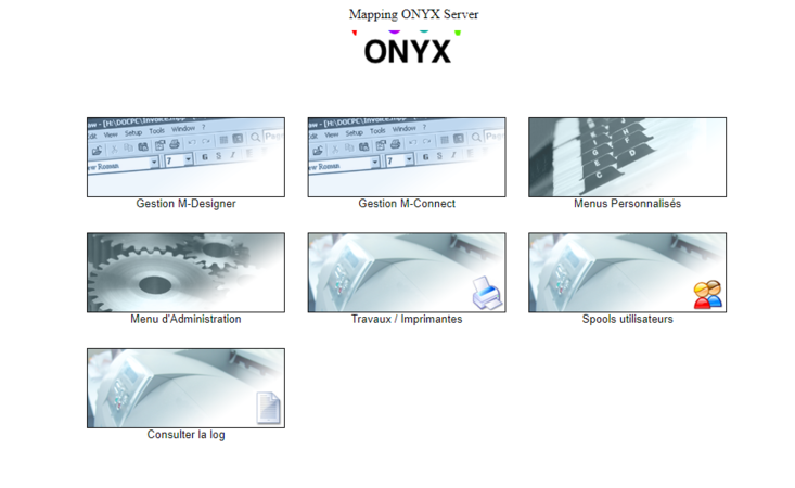
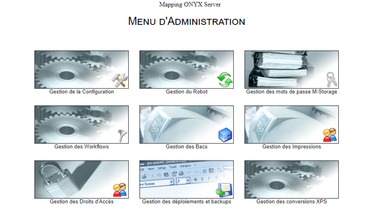
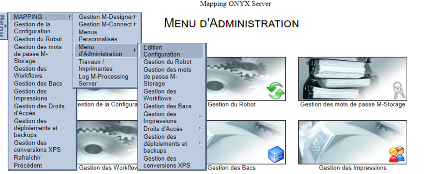
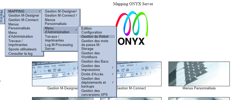
This menu which you can get to from the home page gives you access to:
• all the settings of the solution,
• input points creation and configuration in Onyx Server (Scanfolder robots, listening servers, processing queues),
• execution and routing rules (Workflows) of the output and transfer points of the documents.
This documentation page will touch on the main menus, the other menus will be further discussed in another documentation page.
Configuration management
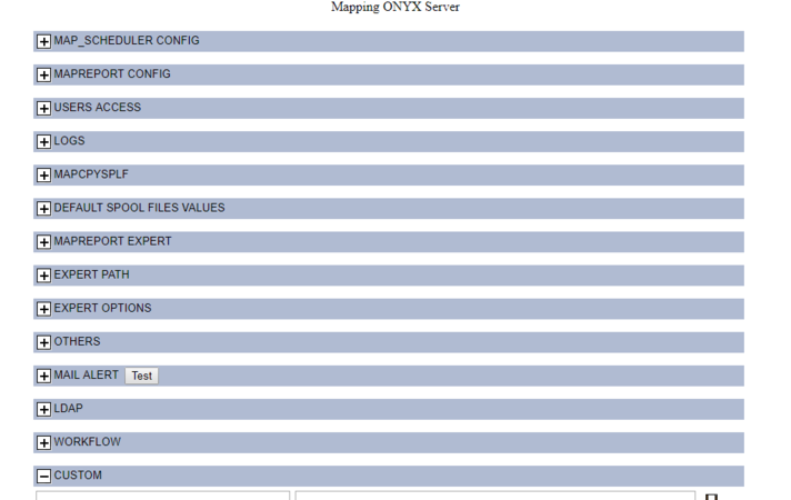
This interface gives you access to all the environment settings to manage the solution from its installation to its general configuration. Most values are given for information purposes and should only be edited with care, by either an advanced user or an admin of the solution. Information is organised in sections, each section identifying the contexts influencing the parameters.
These sections are displayed in condensed mode by default, to open a section and see the corresponding parameters, click on the "plus" icon. An input field allows you to edit the value of each parameter, click on the "save" button to save the changes made. Several changes can also be made at once, every parameter which was edited is then displayed in red until the changes are validated.
All the parameters in these sections are Onyx Server environment parameters which can be used as is in the execution engine (Workflows), as well as in the user scripts launched from the engine.
Example: use the PATH_TEMP parameter to build a temporary file path.
The Custom section which you can access at the bottom of the screen, allows you to create new parameters if needed which you will in turn be able to use in the engine.
To create a new parameter:
- Give a name to the parameter: with alphanumerical characters without spaces, case sensitive (square brackets are not required, they are only added for display purposes),
- Specify a value,
- Save.
Most sections will be seen in detail in this documentation, in their corresponding application contexts.
Managing Robots
This interface manages all the robots configured in the solution, whether they are Scanfolder robots or listening servers.
Upon first installation, the list is blank but it gives access to the Onyx server input points creation/edition menus:
From the perspective of ONYX Server, a robot is an input point in the solution, in other words it is a way for a third-party application to send an execution query. Robots are programs executed as background tasks (Service mode under Windows) to monitor data input, in a folder in the case of Scanfolder robots, or on a network port in the case of listening Servers. Each input file is successively put through the Workflow execution engine to be processed appropriately.
Scanfolder Robots
Introduction
- Scanfolder robots monitor folders in the folder system, to control input files (sent as copies or transferred FTP/SFTP). Files detected in the folder are successively sent (one by one) to the execution engine to be processed according to the rules defined in the Workflows.
- A robot which is configured in ONYX Server can only monitor one folder, in the same way, a folder of the folder system can only be monitored by one Scanfolder robot. You must therefore create and configure as much Scanfolder robots as there are folders to monitor. Each robot is independent from the others, which means that several files can be processed at the same time, but by different robots.
Creating/Editing/Deleting
Clicking the ![]() icon, let's you create or edit robots which were already configured (if they are not being executed).
icon, let's you create or edit robots which were already configured (if they are not being executed).
To configure a robot the following parameters must be specified:
Name = gives a name to the robot.
- This parameter is optional but highly recommended. The name of a robot constitutes an environment variable which is accessible and can thus be used in the Workflows.
- ONYX Server ensures that the names used for the different robots are unique.
Folder to scan = path of the folder monitored by the robot.
- This parameter is required.
- It can point to a network drive or a UNC path (under Windows). Be careful of access rights.
- ONYX Server ensures that the folders scanned by the different robots are unique.
- ONYX Server can create the specified folder if it does not exist.
CMD = action executed on every file detected after it was properly processed by the execution engine.
- This parameter is required.
- Delete: the files detected and processed are deleted from the monitored folder.
- Move: the files detected and processed are moved to another folder, to be archived for example.
Destination folder = destination path of the files processed.
- This parameter is required if the command move was chosen previously.
- ONYX Server ensures that the destination folder is different from the monitored folder.
- ONYX Server can create the specified folder if it does not exist.
Delay = waiting time interval in between which the folder is monitored. Given in seconds.
- This parameter is required.
On Error = defines the behaviour of the robot when a processing error is reported on a detected file.
- This parameter is required.
- Stop: the robot stops and the error file stays in the monitored folder.
- Continue: the robot continues to process the next files while the error file stays in the monitored folder and is renamed with the added suffix _FAILED (keyword configured by Mapping to prevent the robot from processing this file again next time the folder is monitored).
- Retry: the robot continues to process the next files while the error file stays in the monitored folder. Next time the folder is monitored, the robot will try to process this file again.
Workflow = name of the Workflow to execute.
- This parameter is optional. If nothing is specified, the root Workflow is executed by default.
Filter = excludes files from the robot monitoring.
- This parameter is optional.
- Example: *.tmp → the .tmp files in the monitored folder are not processed by the robot.
Accept = restrain the type of files to process.
- This parameter is optional.
- Example: *.xml → .xml files in the monitored folder are the only ones processed by the robot
Notes:
To create a new robot, specify all the needed parameters, click on the "Save" button to add the robot to the server configuration.
To edit an existing robot, edit it or the needed parameters, then click on the "Save" button to edit the robot in the server configuration.
To edit or delete a robot, the latter must absolutely be stopped.
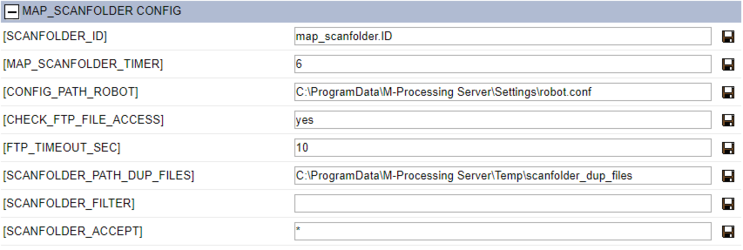
Environment parameters:section MAP_SCANFOLDER CONFIG
This part displays the details of the environment parameters of the Scanfolder robot section.
SCANFOLDER_ID = default naming suffix for temporary files linked to robots (see part Use here-after).
MAP_SCANFOLDER_TIMER = default waiting time interval (in seconds) suggested upon creating a new robot.
CONFIG_PATH_ROBOT = path of the configuration file of the robots.
Example under Linux: /apps/mapping/conf/robot.conf
FTP_TIMEOUT_SEC = maximum waiting time (in seconds) to access an input file in the monitored folder in FTP as the CHECK_FTP_FILE_ACCESS parameter is activated ("oui", "yes", "true" or "1" are accepted).
SCANFOLDER_PATH_DUP_FILES = moving path of the files after processing when the latter have been detected as having already been processed by Onyx Server, in other words path of the files with identical names.
SCANFOLDER_FILTER = exclusion filter for files to process. It can be applied to all the configured robots and can be overloaded by the local parameters of each robot. Several files can be specified, separated by a semi-colon " ; ".
SCANFOLDER_ACCEPT = restriction filter for files to process. It can be applied to all the configured robots and can be overloaded by the local parameters of each robot. Several files can be specified, separated by a semi-colon " ; ".
Use
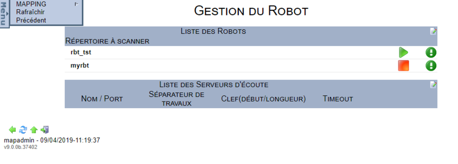
Once the robots created and configured, they are shown in the managing window.
This screen allows you to:
Once started, a robot is a process executed continuously as a background task. The associated ONYX Server binary is map_scanfolder. The list of active system processes (Task manager under Windows / command ps –ef under Linux) displays as much processes map_scanfolder[.exe] as there are robots started.
Note:
Under Windows, robots are installed as Services in the Windows Service Manager. They are registered as such when first starting the robot. The corresponding Service is named based on the name of the robot if it is specified (which is why names need to be unique) or based on the name of the monitored folder (which is why names need to be unique). Example: Mapping_ScanFolder_SCAN_TXT. Every Windows Service created by the robot is configured in manual start by default, however, this can be changed to an automatic system start afterwards.
- Temporary files associated to the robots:
Once started, each robot creates two files in the Onyx Server temporary folder. The first one is named based on the name of the monitored folder with special characters replaced by ‘_’ and the value of the SCANFOLDER_ID ("map_scanfolder.ID" by default) parameter as an added suffix.
Example: E__InputData_TXT_map_scanfolder.ID
The second file is named based on the system number of the associated map_scanfloder[.exe] process.
Example: 75668.pid.
These files are for internal use of the process and are automatically deleted after the robot is stopped. Nonetheless, the Web interface relies on these files to indicate the state of the robots.
- Useful command lines:
To start a robot:
- Linux (after the environment was loaded) /apps/mapping/bin/map_scanfolder -name:SCAN_TXT
- Windows C:\Program Files(x86)\M_Processing Server\Applications\map_scanfolder.exe -name:SCAN_TXT
To stop a robot:
- Linux (after the environment was loaded) /apps/mapping/bin/map_scanfolder -name:SCAN_TXT –stop
- Windows C:\Program Files(x86)\M_Processing Server\Applications\map_scanfolder.exe -name:SCAN_TXT –stop
If the robot is not named, set each parameter that describes the robot as an argument of the previous commands (hence the prior advice on robots unique names)
Listening servers
Introduction
- A listening server type of robot monitors a listening port to control input data (data sent by a remote system by direct transfer in RAW protocol). The robot retrieves the data and rebuilds the files locally, it then sends them successively (one after the other) to the execution engine so that they can be processed according to the rules set in the Workflows.
- A robot which is configured in ONYX Server can only monitor one network port, in the same way, a network port can only be monitored by one listening server. You must therefore create and configure as much listening servers as there are ports to monitor. Each robot is independent from the others, which means that several files can be processed at the same time, but by different robots.
Creating/Editing/Deleting
Clicking the ![]() icon, let's you create or edit robots which were already configured (if they are not being executed).
icon, let's you create or edit robots which were already configured (if they are not being executed).
To configure a listening server the following parameters must be specified:
Name = gives a name to the robot.
- This parameter is optional but highly recommended. The name of a robot constitutes an environment variable which is accessible and can thus be used in the Workflows.
- ONYX Server ensures that the names used for the different robots are unique.
Port = number of the network port the robot listens to.
- This parameter is required.
- ONYX Server ensures that the ports the different robots listen to are unique.
Job separator = character or string of character which divide a wide network stream into several files.
- This parameter is optional.
Key (Length Start) = allows you to add information to the name of the temporary file built by the robot.
- These 3 parameters are optional.
- This information is looked for in the network stream, according to the keyword, while ignoring X characters after the keyword (start parameter) and retrieving N characters (length parameter).
- This information can notably be used in the Workflows as a condition.
Timeout = network waiting time (in seconds).
- This parameter is optional.
- It allows you not to block the network port in the event of a problem coming from the stream transmitter. The robot shuts down the connection after this period of inactivity as it considers that the established connection is not active anymore.
Notes:
To create a new listening server, specify all the needed parameters, click on the "Save" button to add it to the server configuration.
To edit an existing server, edit it or the needed parameters, then click on the "Save" button to edit the server configuration.
To edit a server, the latter must absolutely be stopped.
To delete a robot, the latter must absolutely be stopped.
Environment parameters:section MAP_RAWD CONFIG
In the Mapping Operations Menu which manages configuration, a section is dedicated to listening servers. The details of the environment parameters are given below.
MAPRAWD_ID = default naming suffix for temporary files linked to servers (see part Use here-after).
MAPRAWD_CONFIGFILE = path of the configuration file of the listening servers.
Example under Unix: /apps/mapping/conf/maprawd.conf
MAPRAWD_SERVERSTDIN = path of the file towards which the standard input is redirected (stdin).
MAPRAWD_SERVERSTDOUT = path of the file towards which the standard output is redirected (stdout).
MAPRAWD_SERVERSTDERR = path of the file towards which the standard error output is redirected (stderr).
Use
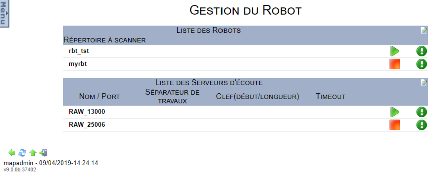
Once the robots created and configured, they are shown in the managing window.
This screen allows you to:
- See the log of a listening server: ![]()
Once started, a listening server is a process executed continuously as a background task. The associated ONYX Server binary is map_rawd. The list of active system processes (Task manager under Windows / command ps –ef under Linux) displays as much processes map_rawd[.exe] as there are robots started.
Note:
Under Windows, listening servers are installed as Services in the Windows Service Manager. They are registered as such when first starting the robot. The corresponding Service is named based on the name of the network port (which is why names need to be unique) and the name of the job separator. Example: Mapping_Rawd_13000, Mapping_Rawd_25006_SEP.
Every Windows Service created by the robot is configured in manual start by default, however, this can be changed to an automatic system start afterwards.
- Temporary files associated to the listening servers:
Once started, each listening server creates a folder in the Onyx Server temporary folder. It is named based on the name of the network port and the job separator with a map_rawd.ID file which contains the number of the associated process.
Example: …\Temp\map_rawd_25006_SEP\map_rawd.ID
- Useful command lines:
To start a robot:
- Linux (after the environment was loaded) /apps/mapping/bin/map_rawd -start -name:RAW_25006
- Windows C:\Program Files(x86)\M_Processing Server\Applications\map_rawd.exe -start -name:RAW_25006
To stop a robot:
- Linux (after the environment was loaded) /apps/mapping/bin/map_rawd -stop -name:RAW_25006
- Windows c:\Program Files(x86)\M_Processing Server\Applications\map_rawd.exe -stop -name:RAW_25006
If the robot is not named, set each parameter that describes the robot (network port and job separator) as an argument of the previous commands (hence the prior advice on robots unique names).
Managing prints
Managing the spooler
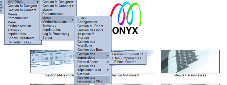
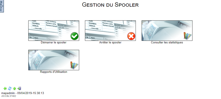
As mentioned earlier, the ONYX Server Spooler is the core of the solution. It manages streams, processings and printers. From the Administration Menu, then Managing prints and finally Managing the Spooler, the following interface allows you to:
- Start the Spooler = Start the Spooler.
- Stop the Spooler = stop the Spooler.
- See statistics = See output statistics.
- Usage reports = See the usage reports of the solution.
Once started, the Spooler is a process executed continuously as a background task. The associated ONYX Server binary is map_daemon[.exe].
Note:
Under Windows, the Spooler is installed as a Service in the Windows Service Manager. It is registered as such when first starting the Spooler. The corresponding Service is named Mapping_Spooler. It is is configured in manual start by default, however, this can be changed to an automatic system start afterwards.
- Temporary file associated with the Spooler:
Once started, the Spooler creates a map_daemon.ID file in its ONYX Server installation folder:
- by default under Windows C:\ProgramData\M-Processing Server\Spooler
- by default under Linux /apps/mapping/spool
- Useful command lines:
To start the Spooler:
- Linux (after the environment was loaded) /apps/mapping/bin/map_daemon start
- Windows C:\Program Files (x86) \M-Processing Server\Applications\map_daemon.exe" start
To stop the Spooler:
- Linux (after the environment was loaded) /apps/mapping/bin/map_daemon stop
- Windows C:\Program Files (x86)\M-Processing Server\Applications\map_daemon.exe" stop
Managing sites and queues
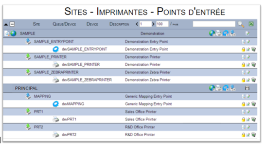
From the Administration Menu, then Managing Prints and finally Managing Sites / Printers / Input points, the interface shown displays the list of all the queues configured in the Spooler, organised per sites.
For example, a SAMPLE site was declared, in which three queues (an input and an output one) are configured. Three other queues are declared outside the site and displayed in a default site called Principal.
From this interface, inside every site, you are able to:
Create a site: Sites are a coherent way to organise queues.
Create an output queue: It will be linked to a physical printer.
Create a costumed processing queue: It runs a client script (shell).
Create a Mapping processing queue: It executes a Workflow.
Important notes:
- All the objets created and configured must have a unique name whatever their type (an output printer cannot have the same name as a site).
- Once created and configured, the name of an object cannot be changed anymore. If necessary, the object must be deleted and recreated.
Definitions
Site:
A site can be defined as a Mapping object, its aim is to organise the different queues. The sites can represent different countries, regions, agencies or stores.
Queue:
A queue can be defined as a Mapping object which receives the list of files to process and organises processings according to priorities. The queue does not establish any other connection with a physical printer. It is an object which only manages a list of files. It is at least linked to a device which does establish connections with physical hardware. If it is in Ready or Suspended state, then the files will not be processed by the device.
Device:
A device is defined as a Mapping object which communicates with the printer depending on specific parameters such as the IP address, protocol, … It must be linked to one queue only. It can be in Ready, Suspended or Error state. In both the last cases, the files will not be processed by the device. Several devices can be connected to one queue (load balancing).
Creating a site
Sites allow you to classify queues in the Spooler to organise the prints managing display into a hierarchy. A site can also be used as a display filter or search filter in the operating view.
To create a site, click on the ![]() button.
button.
Note:
Sites can be created inside other sites, which means you can build a complex display tree system. To do so, use the creation button on the line of the site which is concerned.
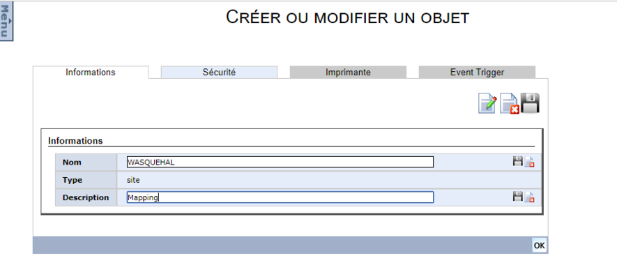
In the input screen, specify each of the following information, validate it by clicking on "save":
- Name = Name of the site (required, it must absolutely be unique).
- Description = optional.
Once the site is configured, saved, click on "OK" (3).
Creating an input point
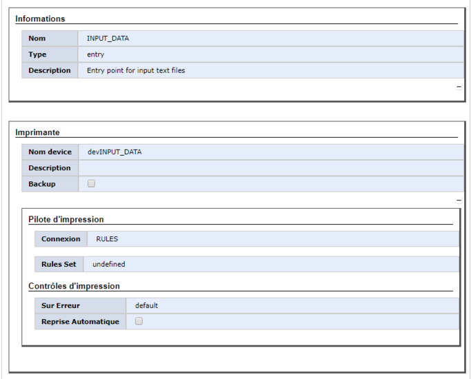
An ONYX Server input point is a queue which runs Mapping processings that are also called Workflows. It is made up of two objects:
- A queue to receive queries (jobs).
- A device, or engine, to handle queries and perform processings.
To add an input point in a site, click on the button on the line of the site which is concerned.
After having specified the needed information, validate it by clicking on "Save".
- Queue
- Name = name of the queue (required).
- Description = description of the queue.
After validating the name, the creation form of the associated device is displayed.
- Printer
- Device Name = name of the associated device (required).
- Description = description of the device.
- Printer driver
- Connection = The default type of driver is RULES and cannot be changed (calls the execution engine).
- Rules set = Choose the executed Workflow in the drop down menu. The root Workflow is executed by default (‘Default’ or ‘Undefined’).
- Print controls
- Upon error = Device behaviour in case of error:
o Default or Stop: in case of error, the current processing stops, the device also stops in error state.
o Continue: the current processing stops in error state while the device continues to process the next queries.
o Ignore: the current processing is considered as done, the device continues to process the next queries. This value is not recommended, except for special cases.
- Error recovery = Error recovery: if activated, an error inducing processing is relaunched.
- Maximum time = maximum time during which a processing in error state is relaunched before really being considered as being in error state. The device behaviour upon error is then taken into account.
Creating a printer
An ONYX Server printer is a queue which communicates with physical printing hardware. It is made up of two objects:
- A queue to receive printing queries (jobs)
- A device or printer, to handle the queries and send data to the physical hardware.
To add a printer in a site, click on the ![]() button on the line of the site which is concerned.
button on the line of the site which is concerned.
Fill in the needed information and validate it by clicking on the "save" button.
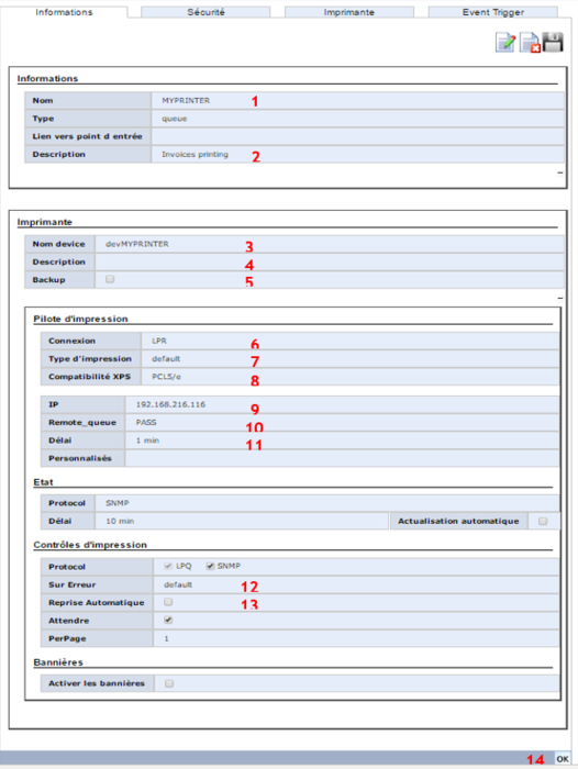
- Queue
- Name (1) = name of the queue (required).
- Description (2) = description of the queue.
After validating the name, the creation form of the associated device is displayed.
- Printer
- Device Name (3) = name of the associated device (required).
- Description (4) = description of the device.
- Backup (5) = if this is activated, it allows you to set a backup printer which will automatically take over the main printer in the event of an error.
- Printer driver
- Connection (6) = type of connection. ONYX Server implements several types of communication protocols, the LPR protocol being the most widespread and use here.
- Type of print (7) = type of print. The default type means that the associated hardware is a physical printer. The MAPPING type indicates communication with another ONYX Server Spooler (remote), and allows you to activate the compression of the exchanged streams.
- XPS Compatibility (8) = XPS compatibility. This allows you to communicate directly with the associated physical printer, in its direct printing language. XPS streams are converted on the fly according to the selected profile, then sent to the printer, without depending on any driver.
- IP (9) = IP address of the physical printer.
- Remote queue (10) = internal name of the physical printer: generally PASS if it is directly connected to the network, or the name of the port on the box (HP JetDirect for instance) if it was used to connect the printer to the network.
- Time (11) = maximum waiting time of a network communication.
- State
Allows you to question the physical printer to see its status displayed in the operating view.
- Print controls
Allows you to question the physical printer to check the status of the print job. This additional communication is described in detail in the User Guide. The default settings can be used at first.
- Upon error (12) = device behaviour upon error:
o default or stop = the current processing and the device stop in error state.
o continue = the current processing stops in error while the device continues processing the next queries.
o ignore = the current processing is considered as done, the device continues to process the next queries. This value is not recommended, except for special cases.
- Error Recovery (13) = Error recovery: if activated, an error inducing processing is relaunched.
o Maximum Time = maximum time during which a print job in error state is relaunched before really being considered as being in error state. The device behaviour upon error is then taken into account.
o Recovery mode: in its entirety or per page.
Once the (basic) configuration of the printer done, save the new object (14).
Printer advanced configuration
Printer driver
The printer driver is configured with all the parameters regarding, solely, the connection to the physical printer for data delivery. The configuration of the printer driver depends on print controls: error report, printer status...
Connection
- LPR (default value, recommended)
Line Printer Remote is the standard connection used for network printers. The Spooler connects to the lpr port of the printer (515) and sends the data. This protocol implements connection and communication controls throughout the delivery process. It is supported by almost all printers and can also communicate with print servers.
- RAW
This is another network protocol, in other words a connection to a port (which has to be specified) followed by data delivery and a log out. This protocol does not implement any control.
- SHELL
Used for queues with the same name, the SHELL type device is not directly connected to a physical printer, it is to a program such as a bat or a shell script depending on the operating system.
- RULES
Used for input queues, the RULES type device is not directly connected to a physical printer, it is to the ONYX Server Workflow execution engine.
- USB
The printer must be connected to a USB port. The name of the port must also be specified.
- SERIAL
The printer must be connected to a serial port. The name of the port must also be specified.
- LOCAL OS SPOOLER (only under Windows)
The device sends the file to a pinter which was declared on the Windows print server. The name of the Windows printer must then be selected in the Remote_queue drop down menu.
- DUMMY
Test type connection. Files are processed but are not really sent.
- IPDS
The printing protocol used is IPDS. This protocol allows you to print AFPDS streams with two-way communication between the server and the printers.
The Email type device is not connected to a physical printer, it is responsible for sending documents received by e-mail.
Print type
- DEFAULT
Default protocol.
- MAPPING
Used to send data to a remote Mapping Spooler, this protocole notably allows you to compress files before they are sent to the remote server.
- AXHIOM (only available for RAW and USB protocols).
This protocol is specific to AXHIOM printers.
- ESCPOS (only available for RAW and SERIAL protocols).
This protocol is specific to EPSON receipt printers.
- SAMSUNG (only available for the RAW protocol).
This protocol is specific to SAMSUNG receipt printers.
- ZEBRA (only available for the RAW protocol).
This protocol is specific to ZEBRA receipt printers (using the LPR protocol by default is recommended for ZEBRA thermal printers).
Fonts resolution
This parameter sets files resolution to create and send AFPDS fonts. The value is given in dpi (240 or 300). This parameter concerns IPDS type connections.
Activate log
This parameter activates IPDS traces. The latter are created in the \afpds\ipds sub-folder of the original ONYX Server folder.
This parameter concerns IPDS type connections.
XPS compatibility
This is the conversion profile to use when sending XPS files. The displayed profile is included in the <label> parameter of the XPSConfig.conf file. If the file to print is in XPS format, then the selected conversion profile is used (to convert PCL, ZPL…). If the file is not in XPS format, then the parameter is ignored and no conversion is done. If there is not any specified conversion profile, the file is sent unconverted (Caution: The result of sending an XPS file to a printer which does not support it is usually unreadable characters printed continuously until the printer bins are completely empty…) This parameter concerns LPR, RAW, IPDS and EMAIL type connections (e.g. to convert to PDF and add attachments).
IP address
This is the destination address of the printer (or print server). The IP address of the peripheral or its DNS name can be used. This parameter concerns LPR, RAW and IPDS type connections. In the case of an EMAIL printer, the IP address of the SMTP server is used.
Remote Queue
Il s’agit du nom de la file d’attente interne de l’imprimante (ou du serveur d’impression). Le nom de la file d’attente dépend du constructeur d’imprimante, le plus commun étant PASS mais il peut également s’agir de RAW, PR1, PR0, PR3, TEXT, mp ou autre. Attention : ce paramètre est généralement sensible à la casse. Dans le cas d’un serveur d’impression, il s’agit de la file d’attente de destination sur ce serveur c’est_à-dire que pour le cas d’un serveur Mapping = le nom de la file d’attente ; pour un serveur d’impression Windows = le nom de l’imprimante ; pour un iSeries = le nom de l’OUTQ… Pour une connexion de type LOCAL OS SPOOLER, la liste de sélection est constituée des noms des imprimantes déclarées dans le spooler Windows. Ce paramètre concerne les connexions de type LPR et LOCAL OS SPOOLER.
Port
Il s’agit du port de connexion à l’imprimante (ou au serveur d’impression). En connexion de type LPR, le port est 515 par défaut (non modifiable). En connexion de type RAW, la valeur la plus courante est 9100. En connexion de type IPDS, les valeurs les plus courantes sont 9100 ou 2501. Ce paramètre concerne les connexions de type LPR (non modifiable), RAW, USB, SERIAL et IPDS.
Délai
Ce paramètre est un timeout de communication réseau pris en compte à chaque étape unitaire de la communication avec l’imprimante physique : connexion, envoi d’un paquet unitaire d’information, réception des acquittements. La valeur * signifie que l’on ne contrôle pas les timeout réseau et que l’imprimante ne tombe donc jamais en erreur. Ce paramètre concerne les connexions de type LPR, USB, SERIAL, LOCAL OS SPOOLER.
Shell
Il s’agit du chemin complet du script exécuté par la device (un .bat sur Windows, un .sh sur Unix ou Linux). Ce paramètre concerne les connexions de type SHELL.
Rules Set
Il s’agit du nom du Workflow exécuté par la device.Ce paramètre concerne les connexions de type RULES.
Personnalisés
Ce paramètre permet d’ajouter des paramètres personnalisés (métadonnées) lors de l’envoi en LPR. Les paramètres disponibles sont ceux de la commande map_lpr (attention à ne pas utiliser un paramètre déjà existant : voir la log de la file d’attente pour plus de détails sur la commande map_lpr exécutée).
Exemple : -sleep:10 = pour faire une pause de 10 secondes entre chaque fichier.
Etat
Il s’agit d’activer ou non le contrôle de l’état de l’imprimante pour affichage dans l’interface du Spooler. Cette récupération de l’état réel de l’imprimante est indépendante du contrôle d’impression qui est effectué en plus de l’envoi des données pour contrôler les erreurs. L’utilisation du contrôle d’état suppose que l’imprimante (ou le périphérique) de destination soit capable de renvoyer ce type d’information.
Attention : si l’imprimante est connectée au réseau grâce à un boitier additionnel (type boitier AXIS ou HP JetDirect), le retour d’information sera fait par le boitier et non par l’imprimante. L’état renvoyé sera donc celui du boitier et non de l’imprimante.
En activant le contrôle d’état, l’interface web du Spooler pourra afficher l’état de l’imprimante (prête, hors-ligne, bourrage papier…).
si l’actualisation automatique est demandée, M-Processing Server récupère l’état d’une imprimante uniquement au moment de l’envoi d’un fichier. L’information affichée correspond dans ce cas à l’état de l’imprimante lors de la dernière impression par Mapping.
Protocole
- NONE
Aucune interrogation sur l’état de l’imprimante n’est faite.
- SNMP (mode recommandé)
Le protocole SNMP est utilisé pour contrôler l’état. Il s’agit du protocole le plus fiable et le plus complet. Il est très bien supporté par la majorité des imprimantes récentes et permet généralement d’afficher le contenu du panneau de contrôle de l’imprimante. Pour contrôler manuellement les capacités SNMP de votre périphérique, la commande mapsnmp[.exe] peut être utilisée.
- LPQ
Le protocole LPQ permet un retour d’information basique sur l’état de l’imprimante. Seul le statut (active ou inactive) est affiché.
- PJL (mode déconseillé, conservé uniquement pour des questions de rétrocompatibilité)
L’état de l’imprimante est renvoyé en utilisant le protocole PJL. Ce protocole est assez complet mais peu fiable car peu normalisé (l’implémentation du PJL est différente en fonction du constructeur voire du modèle d’imprimante). Les messages d’erreur ne sont pas normalisés (d’où les paramètres pour appeler un fichier de message PJL et une langue).
Délai
Cela correspond au délai alloué pour recevoir l’état de l’imprimante. Lorsque l’actualisation automatique est activée, il faut veiller à ne pas mettre un délai trop court pour ne pas saturer le système en trames réseau.
Actualisation automatique
Elle permet de rafraichir automatiquement l’état de l’imprimante même lorsqu’il n’y a pas d’impression. Cela peut être utile pour un opérateur qui gère l’ensemble du parc et veut contrôler l’état général du parc d’imprimantes.
Contrôle d'impression
Le contrôle d’impression est utilisé notamment :
- pour vérifier qu’un fichier a bien été complètement imprimé
- pour effectuer des reprises automatiques si nécessaire
Protocole
- SNMP (mode recommandé)
Le protocole SNMP est utilisé pour contrôler l’état. Il s’agit du protocole le plus fiable et le plus complet. Il est très bien supporté par la majorité des imprimantes récentes. Le SNMP gère notamment le compteur de pages, ce qui permet de vérifier que toutes les pages d’un fichier ont bien été imprimées.
- LPQ
Le protocole LPQ permet un retour d’information basique sur l’état de l’imprimante. Le compteur de pages n’est pas géré ce qui signifie que la reprise automatique ne peut se faire que sur l’intégralité du fichier.
Sur erreur
Cela définit le comportement de la device en cas d’erreur de traitement ou d’impression.
- Default
Comportement par défaut en fonction des paramètres de configuration DAEMON_NO_HOLD_ON_ERROR et DAEMON_DONT_HOLD_ENTRY_ON_ERROR . A la valeur NO, le comportement par défaut des devices est à l’état Stop.
- Stop
En cas d’erreur, le spool en cours passe à l’état erreur. La device Mapping tombe en erreur également. Dans ce cas, toute impression sur cette imprimante est stoppée jusqu’à une intervention de redémarrage de la device Mapping (par l’interface Web ou par commande). Si une imprimante de backup est définie, les fichiers suivants seront imprimés par la device de backup.
- Ignore (déconseiller)
Les erreurs sont ignorées et le spool en cours est considéré comme traité. Le spool suivant est envoyé à l’imprimante.
- Continue
La device reste à l’état prêt et le spool en cours passe en erreur. Le spool suivant est envoyé à l’imprimante.
Reprise automatique
Si la case est cochée, le spooler renvoie le fichier à l’imprimante en cas d’erreur. Il faut, dans ce cas, préciser un délai maximum pour la reprise et un mode de reprise (complet ou partiel). Pendant le temps de la reprise, la device passe en erreur mais le spool reste en cours d’impression. Si la reprise automatique échoue, le spool passera alors en erreur également. Si elle réussit, la device repassera à l’état prêt.
- Délai
Le délai est le temps maximum pendant lequel le spooler relance l’impression.
Attention : certaines imprimantes peuvent imprimer plusieurs fois le fichier.
- Mode
Il permet de définir le type de reprise du fichier :
- Complet : le fichier complet est renvoyé depuis la page 1
- Page min : le fichier est renvoyé à partir de la dernière page imprimée connue moins n pages (n étant défini dans la longueur du chemin papier)
- Page max : le fichier est renvoyé à partir de la dernière page imprimée connue plus n pages (n étant défini dans la longueur du chemin papier)
L’information du nombre de pages renvoyée par l’imprimante n’est pas toujours fiable à 100%. Certaines imprimantes comptent les pages à partir du moment où elles sont reçues dans le buffer et non pas physiquement imprimées. Si l’impression est coupée en cours de traitement et que le compteur de l’imprimante indique 50 pages, il se peut que seules 47 pages aient été physiquement imprimées (les 3 autres étant quelque part entre le bac d’entrée et de sortie = le fameux chemin papier).
Sur d’autres imprimantes (plus rares), le compteur est en retard par rapport au nombre de pages réellement imprimées et il faut décompter quelques pages.
Exemples:
Si la dernière page renvoyée par l’imprimante est la page 50 et que la reprise automatique est paramétrée surpage minavec une longueur de chemin papier de 3 pages, la réédition commencera en page 47. Si la dernière page renvoyée par l’imprimante est la page 50 et que la reprise automatique est paramétrée surpage maxavec une longueur de chemin papier de 3 pages, la réédition commencera en page 53.
Attendre
Le paramètre attendre définit que le spooler attend l’accusé d’impression finale du spool en cours avant d’envoyer le suivant. Il s’agit du mode par défaut. Si le paramètre n’est pas activé, le comptage des pages n’est plus effectif.
Unité de page (PerPage)
L’unité de page dépend du type d’imprimante et du compteur. Elle est utilisée pour vérifier que toutes les pages d’un spool ont été imprimées. Si l’imprimante est de type feuille à feuille (cutsheet), soit la quasi-totalité des imprimantes laser workgroup, alors l’imprimante compte en pages physiques. Il n’y a donc aucun souci de compatibilité avec Mapping qui compte lui aussi en page. L’unité de page est donc à 1 (par défaut). Par contre, pour les imprimantes à papier continu qui utilisent des rouleaux de papier (laser à papier continu, imprimantes matricielles ou thermiques), le compteur est défini en distance imprimée (généralement en pouces). Il faut donc calibrer la taille du papier en précisant l’unité de page. Par exemple, sur une imprimante thermique imprimant des étiquettes de 4 pouces de long, il faut définir une unité de page de 4.
Activer les bannières
Les bannières sont des pages de séparation qui sont ajoutées avant et après le fichier d’impression. Consultez la partie spécifique de ce Guide sur la création et l’utilisation de bannières d’impression.
Paramétrage avancé des files d’attente
Toute file d’attente Mapping, quel que soit son type, propose deux onglets de paramétrages avancés : une partie Sécurité pour la gestion des droits d’accès sur la file d’attente et un gestionnaire d’événements permettant de déclencher des actions particulières.
Remarque :
L’onglet Imprimantes présente l’ensemble des devices configurées et rattachées à la file d’attente de la même manière que l’onglet Information.
Sécurité
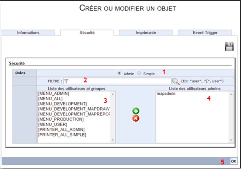
Cet onglet permet d’affecter les droits d’accès à la file d’attente. Cette partie va de pair avec la création des utilisateurs et groupes d’utilisateurs ainsi que la gestion des accès aux menus de l’interface Web.Pour affecter des droits d’accès à une file d’attente, il faut:
(1) Sélectionner le type d’accès :
- Admin : les utilisateurs administrateurs ont tous les droits d’actions sur la file d’attente et ses devices, ainsi que sur tous les travaux de la file d’attente (même ceux dont ils ne sont pas propriétaires).
- Simple : les utilisateurs simples n’ont les droits d’actions que sur les travaux dont ils sont propriétaires. Ils ne voient pas les travaux des autres utilisateurs, même contenus dans la file d’attente.
(2) Utiliser le filtre pour chercher un groupe ou un utilisateur particulier
Remarque :
Par défaut, un filtre sur le caractère ‘[‘ est réalisé, pour ne présenter que les groupes d’utilisateurs (il est en effet généralement conseillé de gérer les droits d’accès sur des groupes d’utilisateurs).
(3) La liste de gauche présente l’ensemble des utilisateurs et groupes disponibles, n’ayant pas encore les droits sélectionnés sur la file d’attente. Sélectionner un ou plusieurs éléments (multi sélection avec la touche Ctrl), puis cliquer sur le ![]() pour affecter les utilisateurs ou groupes à la liste de droite.
pour affecter les utilisateurs ou groupes à la liste de droite.
(4) La liste de droite présente l’ensemble des utilisateurs et groupes d’utilisateurs ayant déjà les droits d’accès (Admin ou Simple) à la file d’attente. Sélectionner un ou plusieurs éléments (multi sélection avec la touche Ctrl), puis cliquer sur le ![]() pour retirer les droits aux utilisateurs ou groupes.
pour retirer les droits aux utilisateurs ou groupes.
(5) Valider l’action une fois le paramétrage terminé.
Event Trigger
Cet onglet permet de monitorer quatre niveaux d’événements sur une file d’attente afin de déclencher des actions particulières.
Types d'événements
Les quatre types d’événements sont :
- Shell_queue : changement d’état d’une file d’attente (de Suspendu à Prêt et vice-versa).
- Shell_device : changement d’état d’une device (de Suspendu à Prêt, de Prêtà Erreur, etc.)
- Shell_spool : changement d’état d’un travail dans la file d’attente (nouveau travail, passage à l’état Prêt, Erreur, Conservé, etc.)
- Shell_user : événement déclenché automatiquement par une action utilisateur (clic sur un bouton).
Les trois premiers événements sont déclenchés automatiquement par le Spooler ONYX Server afin de permettre à l’utilisateur de les monitorer ou non, en faisant appel à ses propres scripts d’actions. Au déclenchement d’un événement, le Spooler exécutera le script paramétré.
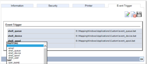
Ci-dessous un exemple de configuration où les trois événements sont monitorés, chacun appelant un script spécifique :
Remarque :
Le paramètre email dans la liste déroulante des événements sert à définir une adresse email qui pourra être réutilisée dans le(s) script(s). Les paramètres de la section SAP sont utilisés dans le cas d’une connexion avec l’ERP SAP.
Variables d'environnement
Comme évoqué précédemment, le Spooler ONYX Server lance lui-même l’exécution des scripts paramétrés. Cela implique que dans les scripts, l’ensemble des variables d’environnement Mapping sont accessibles et utilisables, notamment : PATH_BIN pour le chemin des binaires, PATH_TEMP pour le répertoire temporaire, PMAP_JOBNUM pour l’identifiant unique de travail, etc…
Suivant le type d’événement déclenché, des paramètres supplémentaires sont également accessibles :
- Shell_queue : ensemble des attributs de la file d’attente
| MAP_QUEUE_NAME | Nom de la file d’attente Ex : INPUT_DATA |
| MAP_QUEUE_SITE | Nom du site dans lequel la file d’attente est déclarée
Ex : WASQUEHAL |
| MAP_QUEUE_STATUS | Etat de la file d’attente après déclenchement de l’événement
Valeurs : hold | ready |
| TMAP_QUEUE_LISTEN | Mode d’écoute de la file d’attente
Ex : lpd |
| MAP_QUEUE_PATH_FILE | Chemin de stockage des travaux
Ex : E:\MappingWindows\Spooler\global |
| MAP_QUEUE_PATH_QUEUE | Paramètre obsolète, non utilisé |
| MAP_QUEUE_BACKUP | Nom de la (ou des) imprimante(s) de backup, séparées par une virgule |
| MAP_QUEUE_DESCRIPTION | Description donnée à la file d’attente dans le Spooler
Ex: Entry point for input text files |
| MAP_QUEUE_DEVICES | Liste des imprimantes rattachées à la file d’attente (séparées par une virgule)
Ex : devINPUT_DATA |
| MAP_QUEUE_USERDATA_… | Données « utilisateur » définies pour la file d’attente
Ex : valeurs de shell_queue, shell_spool, … |
| MAP_RESULT | ready |
| MAP_USER_REQUEST | Utilisateur ayant déclenché l’action Valeur : internal_user dans ce cas |
- Shell_device : attributs de la file d’attente (ci-dessus) complétés par l’ensemble des attributs de l’imprimante concernée :
| MAP_DEVICE_NAME | Nom de l’imprimante
Ex : devINPUT_DATA |
| MAP_DEVICE_STATUS | Etat de l’imprimante après déclenchement de l’événement
Valeurs : hold | ready | error |
| MAP_DEVICE_CONNECT | Paramètre obsolète, non utilisé |
| MAP_DEVICE_MODE | Type de connexion
Ex : LPR, RULES, IPDS, … |
| MAP_DEVICE_SUBMODE | Type d’impression
Ex : default, mapping, axhiom, … |
| TMAP_DEVICE_IP | Adresse IP de l’imprimante physique |
| MAP_DEVICE_SHELL | Script ou programme exécuté
Ex : $PATH_BIN/map_809 (moteur de Workflows) |
| MAP_DEVICE_LOGIPDS | Activation ou non des logs IPDS |
| MAP_DEVICE_PORTIPDS | Activation ou non des logs IPDS |
| MAP_DEVICE_FONTRESOLUTION | Résolution des polices (IPDS) |
| MAP_DEVICE_PORT | Port d’impression
Ex : 515, 9100, … |
| MAP_DEVICE_REMOTEQ | Nom interne de l’imprimante physique
Ex : PASS |
| MAP_DEVICE_XPSMODE | Nom du profil XPS de conversion à la volée |
| MAP_DEVICE_TYPESTATUS | Protocole de récupération de l’état
Ex : NONE, SNMP, PJL, … |
| MAP_DEVICE_IMPTYPE | Type de codes PJL pour les messages d’état
Ex : PJL_REF |
| MAP_DEVICE_LANG | Langue des messages d’état (protocole PJL) |
| MAP_DEVICE_PATH_QUEUE | Paramètre obsolète, non utilisé |
| MAP_DEVICE_QUEUE | Nom de la file d’attente à laquelle l’imprimante est rattachée
Ex : INPUT_DATA |
| MAP_DEVICE_TIMEOUT | Timeout de communication réseau (en secondes)
Ex : 600 (pour 10 minutes) |
| MAP_DEVICE_TIMEOUT_STATUS | Délai alloué pour recevoir l’état de l’imprimante (en secondes)
Ex : 10 |
| MAP_DEVICE_REALSTATUS | Etat réel de l’imprimante physique
Ex : Prêt - running-idle |
| MAP_DEVICE_MSGW | Message d’erreur
Ex : Impression échouée |
| MAP_DEVICE_BACKUP | La device est-elle une device de backup ? |
| MAP_DEVICE_MONITOR | Protocole de contrôle de l’impression
Ex : SNMP, LPQ |
| MAP_DEVICE_CUSTOM | Paramètres personnalisés |
| MAP_DEVICE_PERPAGE | Unité de page |
| MAP_DEVICE_RULES | Nom du Workflow exécuté
Ex : Factures.rules.xml |
| MAP_DEVICE_ONERROR | Comportement de la device sur erreur
Ex : continue |
| MAP_RESULT | Le résultat de l’action ayant déclenché l’événement
Valeurs : hold | ready | error |
| TMAP_USER_REQUEST | Utilisateur ayant déclenché l’action
Ex : internal_user dans ce cas
|
Envoyer un fichier dans une file d’attente
Depuis une application tierce, le Spooler ONYX Server est vu comme une imprimante "virtuelle". Pour envoyer des fichiers dans une file d’attente du Spooler, les commandes d’impression sont donc utilisées. ONYX Server dispose de ses propres commandes d’impression : map_lp en local, map_lpr en distant.
MAP_LP en local :
Il s’agit d’une requête directe envoyée au Spooler ONYX Server (c’est le programme map_daemon qui y répond). Deux paramètres sont requis pour cette commande :
- queue:XXX = nom de la file d’attente dans laquelle le fichier sera envoyé.
- data:XXX = chemin complet du fichier à envoyer.
D’autres paramètres sont disponibles sur cette commande (argument --help pour les lister) dont voici les plus courants :
- title:XXX = permet de donner un titre au document dans la file d’attente affiché dans la vue d’exploitation.
- user:XXX = permet de définir le nom d’utilisateur propriétaire du document dans la file d’attente.
- map_hold = le fichier est envoyé avec l’état en attente (ne sera traité qu’après libération).
- map_save = permet de conserver le fichier après son traitement.
- map_retention:NN = permet d’ajouter un délai de rétention (en jours) dans les attributs du spool.
Exemple : les commandes suivantes ajoutent un spool en attente dans la file d’attente INPUT_DATA appartenant à l’utilisateur mapadmin qui possède un délai de rétention de 15 jours et qui passera en état conservé lorsqu’il sera traité.
Sous Windows:
"C:\M-Processing Server\Applications\map_lp" "-queue:INPUT_DATA" "-map_hold" "-map_save" "-map_retention:15"
"-user:mapadmin" "-data:D:\Data\extract\FR_DEMO.txt"
Sous Linux:
"/apps/mapping/bin/map_lp" "-queue:INPUT_DATA" "-map_hold" "-map_save" "-map_retention:15"
"-user:mapadmin" "-data:/opt/data/extract/FR_DEMO.txt"
MAP_LPR en disant :
Il s’agit d’une communication réseau d’impression standard. Les données envoyées à ONYX Server par ce protocole LPR sont réceptionnées en local par le programme map_lpd puis ce dernier ordonne au Spooler d’insérer le document dans la bonne file d’attente.
Trois paramètres sont requis pour cette commande :
- server :NNN.NNN.NNN.NNN = adresse IP (ou nom DNS) du serveur ONYX.
- queue:XXX = nom de la file d’attente dans laquelle le fichier sera envoyé.
- data:XXX = chemin complet du fichier à envoyer.
De plus, suivant la configuration, le server d’écoute LPD d'ONYX Server n’utilise pas forcément le port 515 (port d’impression standard donc peut-être déjà utilisé par une autre application). Dans ce cas, il faudra préciser le port réseau Mapping par l’argument : -port:NNN .
D’autres paramètres sont disponibles sur cette commande (argument --help pour les lister), les plus courants étant identiques à la commande map_lp .
Exemple : les commandes suivantes ajoutent un spool en attente dans la file d’attente INPUT_DATA appartenant à l’utilisateur mapadmin qui possède un délai de rétention de 15 jours et qui passera en état conservé lorsqu’il sera traité.
Sous Windows:
"C:\App\Mapping_client\map_lpr" "-server:192.168.217.57" "-queue:INPUT_DATA" "-map_hold" "-map_save" "-map_retention:15"
"-user:mapadmin" "-data:D:\Data\extract\FR_DEMO.txt"
Sous Linux:
"/apps/mapping_client/map_lpr" "-server:192.168.217.57" "-queue:INPUT_DATA" "-map_hold" "-map_save" "-map_retention:15"
"-user:mapadmin" "-data:/opt/data/extract/FR_DEMO.txt"
