OPALE - 10.0 - Usage
Dynamic Part (Map)
Definition:
The "MAP" part of a project corresponds to the dynamic part of designs that are made according to the datastreams processed by the template. The main elements which can be placed in this part are data files printable information.
To design this part, select the "Map F" tab (and "Map B" for the duplex of the document). In this view, elements of the "Draw" part are displayed as watermarks so that positioning the data to be printed is easier.
"Spooled File"
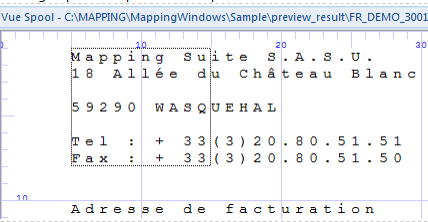
To retrieve and identify data to be printed, designing a Designer project is done using an example file. This example file is an image of the production spooled file to format.
Designer supports two types of data files in native mode: paginated text files and XML files in Mapping format. Input file types are configured in the project properties.
Text files usually have a ".PAG" extension because they need to be paginated: the DESIGNER application does not manage pagination in SPLF mode.
Text files can be paginated by running the « MAPPAGIFS » command in OPALE Server where an argument specifying the number of lines per page ("Overflow") will be given.
XML files need to respect a particular syntax so that the application can properly process them.
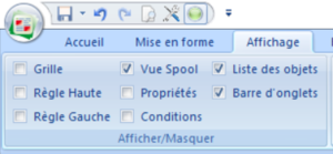
To open and display an example file in DESIGNER, the spooled file view needs to be activated in the "Display" Menu.
In the "Home" tab, click on "Load spooled file" and select the file you want to load in the application.
The spooled file view then displays the data from the spooled file to format.
Note:
To help you design your project, you can preview the result without having to print the document.
To do so, click on the corresponding button in the "Home" menu.
XML mode: syntax and specifications
In XML mode, the design principles are the same and are put in application using an example file loaded in the application.
[
[File:ModeXML.PNG|300px|center|sans_cadre]]
Once the document is loaded, do not forget to check that the mode = XML in the project properties.
The spooled file view is then called the XML view and displays the content of the file in a tree view.
Data Structure :
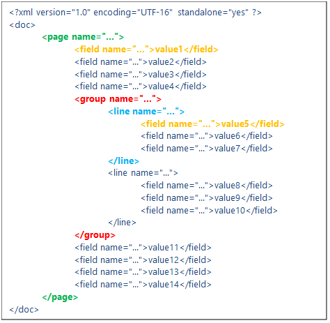
XML files that are processed by Designer in native mode have to respect a specific pattern and syntax, such as:
- The <page name="..."> … </page> tags mark out the pages of the document. In the last example, there is only one page.
- The <field name="...">value1</field> tags correspond to singular information (the equivalent of ‘zones’/'fields' in Designer).
- The <group name="..."> … </group> tags refer to a particular number of lines which contain zones, such as a ‘group’ in Designer.
- The <line name="…"> … <line> tags correspond to the lines inside of these groups.
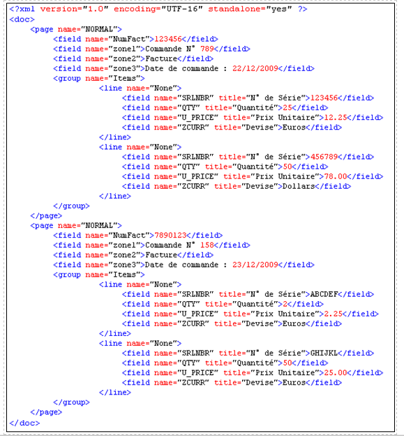
If we were to use this structure with a paper invoice:
<page name="..."> … </page> corresponds to the pages of the invoice.
<group name="..."> … </group> marks out the body of the invoice (from the first line to the last).
<line name="…"> … <line> describes every line in the body of the invoice.
<field name="...">value1</field> can correspond to two things:
- If this tag is on the outside of a group, that is to say on the outside of the <group> </group> tags, it can correspond to singular information in the invoice. In which case, value1 corresponds to the invoice number in the header, for instance, or to the client number, the type of invoice, etc.
- If this tag is inside a group, value1 corresponds to the value of the zone in the line. For instance, the product code, its name, price, etc.
XML pattern specifications:
The specifications needed for Designer to process the file are the following:
- The XML header needs to specify the file encoding.
Example: <?xml version="1.0" encoding="UTF-16" standalone="yes" ?>
- The root tag of XML data needs to be called "doc".
- All tags mentioned hereafter need to have at least one attribute named "name". Information will be identified, retrieved and formatted by the application via the use of this attribute.
- The tags and attributes names are case-sensitive and need to be written in lowercase letters.
- For the application to access it, data must be placed in pages in between the <page name="…"> and </page> tags. One document can contain several pages.
- Inside a page, data is organised per singular fields (<field name="…"> tag), or per information groups (<group name="…"> tag)
- Information groups are composed of lines (<line name="…"> tag)
- The lines contain singular informations (<field name="…"> tag)
Note:
XML data can be placed on the outside of a page as information linked to the overall document and not to the page in particular. However this data will not be accessible to Designer and thus cannot be processed to design the document. Nonetheless, this data can be used by in the Opale Server engine.
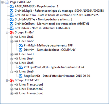
XML view in Designer:
An XML example file is loaded in DESIGNER in the same way that is use to load a text file. In the XML view, data is displayed as a list of elements.
Premiers Éléments Dynamiques :
1.Zone:
Élément principal par excellence, une zone permet de récupérer de l’information dans les données en entrée, afin de les positionner et de les mettre en forme dans le document graphique final.
En mode texte, l’information est identifiée par 3 données : un numéro de ligne, un numéro de colonne et une longueur. En mode XML, elle est identifiée par le nom du champ XML (balise field).
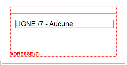
Une Zone ne peut lire qu’une seule ligne à la fois. Dans l’espace de conception, elle est représentée par son nom entouré d’un rectangle bleu :
Pour créer une zone :
Sélectionner la zone à récupérer directement dans le spool puis utiliser le « glisser-déposer » pour la placer sur l’espace de conception :
Une fois placée, la vue Propriétés s’affiche, pour renseigner les informations de la zone :
Nom :
- Nom de la zone : information interne à Designer, permettant d’identifier les différents objets dans le projet
- Champ XML : nom du champ XML identifiant l’information (en mode XML uniquement)
- Labels avant/après : possibilités d’ajouter du texte avant et/ou après l’information récupérée
Position dans le document :
- Permet de modifier le positionnement de la zone dans la page
Position :
- Identification de la position de l’information dans le spool de données : ligne, colonne, longueur.
- Permet également d’extraire une certaine quantité d’information en mode XML
Type de donnée :
Permet de définir comment l’application Designer doit traiter l’information récupérée (voir ci-après)
Police :
- Permet de paramétrer toutes les options de mise en forme de l’information : police, taille, couleur, cadrage, orientation, etc.
Remarque :
Le « glisser-déposer » depuis la vue Spool complète automatiquement la position des données en fonction de la sélection effectuée. Elle peut être ajustée si besoin.
La création d’une zone peut également se faire par l’icône présent dans la barre d’outils « Mapping ». La position des données devra alors être renseignée manuellement.
Types de zones : Designer propose diverses options de traitement de l’information .
- Texte : permet d’imprimer du texte simple
- Code barre : permet d’encoder et d’imprimer des codes-barres
- Outils : permet d’insérer un numéro de page, des images, …
- Archive : permet d’indexer le document pour l’archivage (zones non imprimées)
- Mémoire : permet de mémoriser des informations (non imprimées) pour les réutiliser plus tard
- Graphique : permet de concevoir des graphiques
- Conversion : permet de convertir des nombres (Euro à Dollar par exemple)
Remarque :
Pour insérer un retour chariot dans une zone, il faut entrer \x0A dans le champ "Label après" des Propriétés de la zone.
2.Groupe :
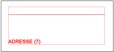
Un groupe permet de récupérer plusieurs lignes d’un spool. Il est caractérisé par une ligne de début et une ligne de fin. Sur l’espace de conception, il est représenté en rouge :
Un groupe peut être fixe (lignes de début et de fin fixes) ou variable (lignes de début et de fin variables).
Pour créer un groupe fixe :
Sélectionner le bloc de lignes à récupérer directement dans le spool, puis à l’aide d’un « glisser-déposer », placer le groupe sur l’espace de conception
La vue Propriétés s’affiche, pour renseigner les informations du groupe :
Zone :
- Nom : information interne à Designer
- En mode XML, il s’agira du nom de la balise « group »
Position dans le document :
- Identification des lignes de début et fin du bloc d’information à récupérer
- Décalage : position d’impression de la première ligne par rapport au groupe
Option :
- Conditions exclusives : pour une ligne du groupe, une condition vraie s’exécutera de manière exclusive, sans tester les suivantes.
Variable :
- Permet de changer le type de groupe : de fixe (les lignes de début et de fin sont statiques) à variable (les lignes de début et de fin sont variables, définies par des conditions)
Remarque :
Le « glisser-déposer » depuis la vue Spool complète automatiquement les informations ligne de début et ligne de fin. Elles peuvent être ajustées si besoin.
La création d’un groupe fixe peut également se faire par l’icône présent dans la barre d’outils « Mapping ». Les lignes de début et de fin devront alors être renseignées manuellement.
Si l’utilisateur demande un aperçu, aucune information ne sera imprimée. En effet, un groupe ne définit que des bornes entre lesquelles de l’information doit être récupérée dans le spool.
Entre ces 2 bornes (ligne de début et ligne de fin), il convient maintenant de déterminer la position des informations à récupérer et imprimer, en ajoutant des zones dans le groupe :
Pour créer un groupe variable :
Le principe du groupe variable est identique au groupe fixe : récupérer plusieurs lignes d’information dans le spool. Le groupe fixe sera utilisé lorsque les informations à récupérer sont positionnées de manière fixe dans les spools (toujours au même endroit), alors que le groupe variable permettra de récupérer des informations dont le positionnement n’est pas fixé à l’avance.
Un groupe peut être variable :
- en taille : les lignes de début et de fin sont déterminées dynamiquement par conditions
- et/ou en position d’impression : les groupes variables peuvent être chainés les uns à la suite des autres, le groupe n+1 commençant à s’imprimer dès que le groupe n est terminé.
Pour créer un groupe variable, cliquer sur l’icône , puis dessiner le groupe sur l’espace de conception. La vue Propriétés s’affiche, pour renseigner les informations du groupe
