ONYX - 9.0 - Usage
ONYX Designer Advanced features
Sommaire
Advanced features
Barcodes
Creating barcodes
To create a barcode in Designer, create a zone type Barcode and select the barcode sub-type you want.
Types of barcodes
- EAN 8 This barcode is used to track logistics units and identify stock keeping units. The eight characters version is used for small sized packages. The data must contain seven digits. The eighth character is a check digit which is calculated by the computer.
- EAN 13 This barcode is used to track logistics units and identify stock keeping units. In an EAN 13 code, the first two characters are the identifiers of the country of origin, the other 10 are the data and the last is the check digit which is calculated by the computer. The data must contain 12 digits.
Code 39
This barcode is used to encode alphanumeric data. It is used in almost every industry except the retail sector. The data may be of variable length and may contain letters and digits.
The information can be of any length and contain digits, uppercase letters and the "space", "plus sign", "minus sign", "division", "dot", "percentage" and "dollar" characters.
- Code 128 allows general alphanumerical data and ASCII data to be encoded. These codebars are used in numerous industries for stock management purposes. The data is of variable length. The Code 128 C must contain an even number of characters (otherwise a zero is added at the beginning of the barcode) and may only contain digits. The Code 128 B accepts all ASCII characters, whereas the Code 128 A accepts only some of them. The information to encode can be of any length and composed of:
- Optimised: digits, uppercase letters, lowercase letters, printing or non-printing ASCII characters (0 - 128), and all the function signs and characters provided by the Code 128 in the A, B and C code sets, with systematic length optimisation
- N/optimised: digits, uppercase letters, lowercase letters, printing or non-printing ASCII characters (0 - 128), and all the function signs and characters provided by the Code 128 in the B code set, without length optimisation
- Digital: digits and check character provided by the Code 128 in the C code set, with systematic length optimisation
- Code 2/5 interleaved This encoding of numbers is used to enter information about the density of products, in response to precise specifications. The security of this symbology is weak, except when using optional security measures (check character, messages of fixed length that are checked when scanning).
- Although the length of the barcode is unlimited in terms of the number of characters, the principle of interleaving requires the following:
- An even number of digits when the optional check character is not used
- An odd number of digits when the optional check character is used
- Code 2/5 industrial This old symbology was frequently used in industry, particularly the automotive industry. The security of this symbology is weak, unless it is used with messages of fixed-length and checked when scanning.
The data must contain 1 to 32 digits
- Digital information encoding that is designed for its ease of use
- Development or modification of pre-existing applications
- EAN128 Alpha n/optimised Code GS1-128 Used to identify dispatch units (pallets or cartons, possibly).
- Encoding of alphanumeric information,
- Variable length,
- Continuous bidirectional self-checking.
- EAN128 digital Code GS1-128 Used to identify dispatch units (pallets or cartons, possibly)..
- Encoding of digital information,
- Variable length,
- Continuous bidirectional self-checking.
- PDF 417 Used in every sector of activity. The PDF417 code is the only two-dimensional barcode that can be scanned using a simple linear scan (1D) due to the fact that, as stacked linear symbology, it has the features of linear barcodes as well as those of two-dimensional ones.
- Two-dimensional,
- Alphanumeric 2000 length,
- Eight levels of security.
- Data Matrix This code can encode up to 2335 characters. Various types of encoding are available (ASCII, C40, text and Base 256). The default mode is the automatic mode which can be used to optimise the encoding by swapping from one mode to the other depending on the data. It also has an error detection/correction system to repair any damage.
- Postnet The Postnet barcode is used by the United States postal service. It has been replaced by the USPS or Intelligent Mail barcode.
- Planet The Planet barcode is used by the United States postal service. It has been replaced by the USPS or Intelligent Mail barcode.
- QR Code It has the particular feature of being able to encode a very large number of characters (7336 in numeric mode). This type of barcode is very widespread in Japan. There are four types of encoding (alphanumeric, numeric, bytes, Kanji) for compressing the data by varying degrees depending on the type of data. By default, an automatic mode is used to choose the encoding method that will give the best compression rate (switch of mode while processing). Error detection/correction codes are added to the data, which are used to prevent the loss of data in the event of damage. There are four levels of error detection/correction.
- MaxiCode The MaxiCode barcodes, developed by UPS - United Parcel Service, are defined by the ISO 16023-2000 standard. Unlike the others, it has a set size, which limits the number of characters to be encoded. Indeed, the maximum number of characters is 93 alphanumeric characters or 138 numeric characters. There are two types of encoding. The first only encodes a string of characters containing data according to a conventional type of encoding and a standard type of error detection/correction. The second type encodes the following three fields in addition to the string of data: the country which is encoded using 3 digits according to the ISO 3166 standard, the postal code which is encoded using 6 characters and finally a type of service using 3 digits. These three fields are encoded using an extended error correction mode contrary to the string of data whose correction mode is standard.
- Japan Postal The Japan Postal barcode is used by the Japanese postal service.
- Codabar (NW7) In Japan, the Codabar Monarch is also called NW-7. The relatively simple composition of the Codabar Monarch means that it is frequently used to encode serial numbers for applications involving blood bank transfusion services, home deliveries, libraries, etc.
- USPS USPS = United States Postal Service. The more commonly used official name is the Intelligent Mail Barcode. It is the new American postal barcode, which is to replace the Planet and the Postnet. The Intelligent Mail barcode is a 4-state barcode composed of 65 bars.
- UPC-A The UPC-A barcode est un équivalent américain du code à barres EAN13, dont le premier chiffre serait 0. is a U.S. equivalent of the EAN13 barcode, the first digit of which is 0. It is used primarily to identify products in store. The UPC-A barcode can encode 11 digits, a number system, five digits for the Manufacturing Code and five digits for the product code. A 12th digit is calculated using the first eleven in order to act as a check digit.
- UPC-E The UPC-E barcode is a short version of the UPC-A barcode, in which the ten digits of the UPC-A barcode (manufacturing and product code) are reduced to six digits by removing superfluous zeros. With the Number System and the check digit, a UPC-E barcode is therefore composed of eight digits. M-Designer can be used to include UPC-A (11 digits) barcodes in the UPC-E format as well as a code reduced to 6, 7 or 8 digits.
- MSI The MSI barcode is used primarily for stock management, marking storage containers and shelving in warehouse environments. An MSI barcode uses one or two check keys calculated using the Modulo 10 or Modulo 11 methods and is used to encode numeric values of indefinite size. Designer can encode using either a Modulo 10 check key, a Modulo 11 check key, two Modulo 10 check keys, or even a Modulo 11 check key followed by a Modulo 10 check key.
The size of the barcode
The size of the barcode can be defined in the following two ways:
- The first involves choosing the Fit the area option in the Properties view, lin which case the barcode will adjust as well as possible to the size of the zone, according to its standard
- If the Fit the area option is unticked, the size of the barcode can be set by the size of the font of the zone. This size affects the width and the height of the code. The height can be reduced by reducing the percentage of the height setting of the zone.
Combined data
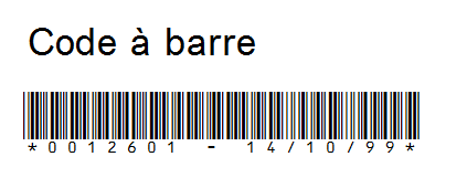
It is possible to combine data found in different places in the spooled file within a single barcode. In order to achieve this, it is necessary to create as many memory zones as there are elements of data to be retrieved from the spooled file and then all these zones must be combined in the label of the barcode zone.
- In the Map F tab:
- In the Properties view:
- In this example, the Memory zone have the values:
- MEM_FACT : 0012601
- MEM_DTFACT : 14/10/99
- Outcome:
It is also possible to add text that is not found in the spooled file using the Memory zones (detailed in 6.4.a.3 Types of zones) : [[MEM1]]TEXT[[MEM2]].
If you use replacement zones in a Barcode zone, the length of the barcode must be equal to 0.
Special case: EAN128
The encoding of the EAN128 is identical to the encoding of the Code128. That is why we use the same fonts. The difference is that the EAN128 is structured in order to standardize the information that it contains. To achieve this, an AI (Application Identify) is inserted between each piece of information, which is used to identify the data encoded.
Structure of the EAN128: START FNC1 AI DATA (FNC1) AI DATA .... (FNC1) AI DATA CRC END
FNC1: Separator character of the EAN128.
AI: Application Identifier, is used to encode several standardized elements of information in one code (date+time+etc.).
The first FNC1 is automatically added by M-Designer. It is required as it is used to differentiate an EAN128 barcode from a CODE128 barcode.
However, the following FNC1 are optional. Indeed, they are only required when the previous element of data does not have a fixed length, in which case they are used to separate each element of data.
If you want to insert the FNC1 character, you have to put the {FNC1} character sequence in your spooled file. These characters will automatically be replaced with FCN1 characters by MAPPING.
Ex: SPOOL ----> MAPPING
AI DATA ----> START FNC1 AI DATA CRC END
AI DATA {FNC1} AI DATA ----> START FNC1 AI DATA FNC1 AI DATA CRC END
If you cannot change your spool to add the "{FNC1}" characters or if you want to combine several elements of data that are located in different places in the spooled file (see previous paragraph: 8.1.b. Combined data), you can use the memory zones.
Special case: code 128
There are three encoding modes for 128 barcodes:
- mode A (alphanumerical),
- mode B (alphanumerical). The code 128 Alphanumeric encodes in B mode,
- mode C (numerical). The code 128 Alphanumeric encodes in C mode.
The code 128 Alphanumeric Optimized switches from B mode to C mode automatically in order to optimize the size of the barcode.
However, your barcode may have to comply with a specific type of formatting, i.e. a certain number of characters in A, B or C mode.
For example, the barcode that corresponds to the mail tracking ID of "La Poste" contains 13 characters. The first three must be encoded in B mode and the last ten in C mode.
In order to create this barcode using Designer, you must create a "Code 128 N/Optimisé" type zone and then enter a formatting screen in the Advanced options of the zone.
Example:
For the following data: 1J45034500751
You want to encode:
- the first three characters (1J4) in B mode
- the last ten characters (5034500751) in C mode
Your formatting mask must therefore be BBBCCCCC.
You will notice that although there are ten digits to be encoded in C mode, there are only five 'C's in the formatting mask. This is due to the fact that one character in C mode encodes two digits.
Special case: 2D Codebars
Currently, MAPPING manages four types of 2D barcode: PDF417, DATA MATRIX, QR CODE and MAXICODE.
If "Fit the area" is checked, the "Barcode width" setting is used to change the size of the barcode. In this case it should be noted that the size of the barcodes can vary in height and width depending on the content to be encoded.
The benefit of 2D barcodes is being able to encode a number of important pieces of information. If the data that you need to encode is located in different places in the spool, go to section 8.1.b. Combined data to combine them in a single barcode.
QR code
The QR CODE barcode was developed according to the International ISO/IEC 18004 standard. It has the particular feature of being able to encode a very large number of characters (7336 in numeric mode).
This type of barcode is very widespread in Japan. It is already used in the industry, but has also been adopted by the general public eversince mobile phones know how to decode it.
There are four types of encoding (alphanumeric, numeric, bytes, Kanji) for compressing the data by varying degrees depending on the type of data. By default, the automatic mode is used to choose the encoding method that will give the best compression rate (switch of mode while processing). For example, let us assume that the beginning of the string contains alphanumeric type data. As soon as the program detects a string of at least 13 numeric characters, it changes encoding mode.
Error detection/correction codes are added to the data. These codes prevent losing data through damage. There are four levels of error detection/correction. By default, level three is used, whose codes use approximately 25% of the final barcode.
Advanced options available:
- Barcode width: Value between 1 and 15 specifying the size of the barcode.
- Error Level: (7%, 15%, 25% and 30%).
- FCN1:
- ECI protocol not implemented.
- ECI protocol not implemented, FNC1 implied in first position.
- ECI protocol not implemented, FNC1 implied in second position n the last case, a separator character (Application identifier) must be specified.
- Application Identifie: Separator character, used only with the implicit FCN1 in second position.
- Type of encoding:
- AUTO: Automatic encoding of the data with a mode change depending on the data.
- ALPHA: Alphanumeric encoding.
- NUMERIC: Numerical encoding.
- BYTE: Encoding in bytes.
DATAMATRIX
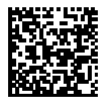
The Datamatrix barcode is defined by the International ISO/IEC 16022 (ECC200) standard. This code can encode up to 2335 characters.
Various types of encoding are available (ASCII, C40, text and Base 256) and the default mode is the automatic mode that can be used to optimize the encoding by swapping from one mode to the other depending on the data.
It also has an error detection/correction system to repair any damage.
Advanced options:
- Barcode width: Value between 1 and 15 specifying the size of the barcode.
- Type of encoding :
- AUTO: Automatic encoding of the data with a mode change depending on the data
- ASCII: The ASCII encoding is a tacit plan for encoding the ASCII data.
- C40: C40 encoding transforms 3 alphanumeric characters into two code words.
- TEXT: The Text encoding is used to encode the lowercase characters.
PDF 417
The PDF 417 is defined by the International ISO/IEC 15438 standard. This type of barcode can encode up to 2700 numeric characters.
There are three types of data encoding (alphanumeric, numeric and bytes). The automatic mode chooses the best compression rate and changes the mode while encoding.
There are also eight levels of error detection/correction mode. In automatic mode, the level is chosen according to the number of characters to be encoded.
Advanced options:
- Barcode width: Value between 1 and 15 specifying the size of the barcode
- Error Level:
- AUTO: choix automatique.
- 0 - 8
- Compact mode: Activation of the compact mode or not.
- Ratio: Used to determine the height/width ratio of the barcode.
- Fixed columns: Used to define the number of columns.
- Fixed rows: Used to define the number of rows.
The selection of a ratio prevents you from specifying the number of rows and columns.
UPS MAXICODE
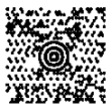
This type of barcode, developed by UPS - United Parcel Service, is defined by the ISO 16023-2000 standard. Unlike the others, it has a set size, which limits the number of characters to be encoded. Indeed, the maximum number of characters is 93 alphanumeric characters or 138 numeric characters.
There are two types of encoding:
- The first only encodes a string of characters containing data according to a conventional type of encoding and a standard type of error detection/correction.
- The second type encodes three other fields stored in three of Designer's memory spaces, in addition to the string of data. These fields are: the country encoded using 3 digits in accordance with the ISO 3166 standard (called MAP_countr), the postal code encoded using 6 characters (MAP_zipcod) and finally a type of service using 3 digits (MAP_servic). These three fields are encoded using an extended error correction mode contrary to the string of data whose correction mode is standard.
Advanced options available:
- Barcode width: Value between 1 and 15 specifying the size of the barcode.
Automating
Automating Designer processes allows you to create image files corresponding to the preview of a project as well as generate a project or an association of projects. All this can be done in order line, in hidden mode or not.
The principle is to build the order with a .BAT or a remote order, for example.
- -InFile: .PAG or .XML file to map.
- -OutFile: Output image file.
- -ProjectFile: Projet to open (.MPP).
- -ProjectAsso: Project association to generate (.MPA).
- -MPIFile: .MPI file to open (MAP tab).
- -MPWFile: .MPW file to open (DRAW tab).
- -Hide: To launch Designer in hidden mode.
- -Color: Use of colour or not to create the image.
- -Rotation: rotation angle of the image (default: 0).
- -Resolution: Image resolution (default: 300).
- -Specimen: Adding a text above the image (text to specify in the argument).
- -Mode: Choice of the SPOOL or XML mode (default SPOOL).
- -Generate: To start generating the project indicated in the argument.
- -FtpUse: 0 = does not use FTP; 1 = uses FTP.
- -FtpFolder: FTP folder.
- -FtpLogin: FTP login.
- -FtpPassword: FTP password.
- '-FtpIPAddress: IP address of the server.
- -ShareFolder: Shared folder.
- -ServerName: Name of the server (description).
- -Rename: changes the FORMAT and SEQUENCE of the project using its name. Ex: Invoice00010.mpp.
Example 1: Project generated in PCL, in color and 300 dpi
C:\Mapping\M-Designer\M-Designer.exe "-Hide" "-ProjectFile:C:\Mapping\M-Processing_Server \Import\docpc\test.mpp" "-Generate"
When using the "-Generate" setting (indicating a project generation), the "-ProjectFile :" or "-ProjectAsso :" setting must be present to identify the project as to be generated.
If both settings "-ProjectFile :" and "-ProjectAsso :" are present, the project will take priority for the generation and the association of projects will be ignored.
Example 2: creating a colour BMP image, with a 90° rotation, in 203 dpi and with the word SPECIMEN overlaid
C:\Mapping\M-Designer\M-Designer.exe "-InFile:c:\test.xml" "- OutFile:c:\image.bmp" "-ProjectFile:C:\ Mapping\M-Processing_Server \Import\docpc\test.mpp" "-Hide" "-Rotation:90" "- Resolution:203" “-Color” "-Mode:XML" "-Specimen:SPECIMEN"
The "-InFile" and "-ProjectFile" settings are mandatory to create an image.
If "-OutFile" is missing, the output file takes the name of the input file with the .BMP extension.
The default mode is SPOOL. If the input file is an XML file, you have to specify the mode.
Caution: The quotation marks around each parameter are required.
Replacing characters
The objective is to explain how to replace a string of characters in the input file with another string of characters.
The operating principle involves using a text file as a conversion chart between the value to be replaced and the new value.
The following is required in order to use the conversion chart:
- Define the zone using the Type mode = Text / Sub-type = Substitution.
- Finish and generate the template.
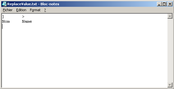
- Open the ReplaceValue.txt file in a text editor (like Notepad, but not Word). The syntax of the file is:
Value to be replaced Tab New Value
In this case, the "]" character is replaced with the ">" character and the "Nom" character is replaced with the "Name" character (if the value to replace is located in a Text\Substitution type zone).
- Save the ReplaceValue.txt file in the lgobitmap Mapping sub-folder (by default /apps/mapping/import/lgobitmap on Unix)
Drawing a table
Drawing a static table
To create a perfectly drawn and aligned table without using the Static Table tool of the Overlay view:
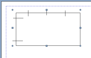
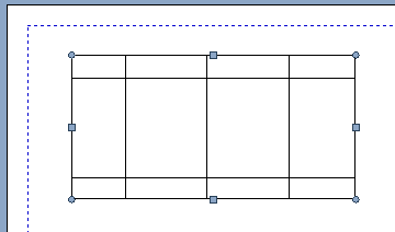
- first, draw the rectangle that will act as the borders of the table,
- draw the vertical lines to create columns,
- draw horizontal lines to create lines if necessary (column headers for example),
- finally select all elements of your table and press the lowercase "a" on your keyboard:
Note:
This tip also applies to designing the Dynamic part of a project. You can draw a table inside a group in dynamic view, and place an execution condition on a horizontal line for instance, to draw a line dynamically for every new data row.
Drawing a dynamic table
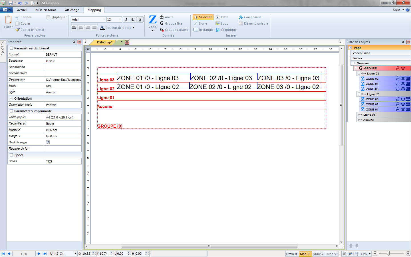
As mentioned in (6.4.b.2. Creating a fixed group), the table mode allows the zones of the group to act as cells of a table. The zones of one line are automatically linked.
Note:
Resizing or moving a zone impacts the size and position of the adjacent zones.
The lines of the group (or conditions) are represented visually in the designing window. The zones are vertically distributed according to their line.
Drawing a graph
In the Map tab:
- Create a graph in the Graph tab:
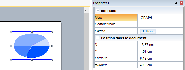
- Name it (here, "GRAPH1"):
From there, the complex graphcan be built in two different ways, detailed below.
By selecting zones one by one
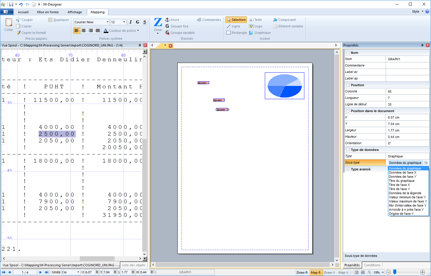
- In the spooled file, select the zones which will be used in the graph,
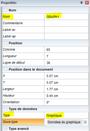
- In the Properties for each defined zone:
- Name them all with the same name as the graph (which is "GRAPH1" here)
- Enter the Type = "Graph ":
- Depending on the use made of the area in the graph, select the corresponding Sub-type in the list:
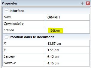
- Go to the Graph Properties and click on Edition:
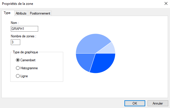
- Set your graph by choosing from the tabs:
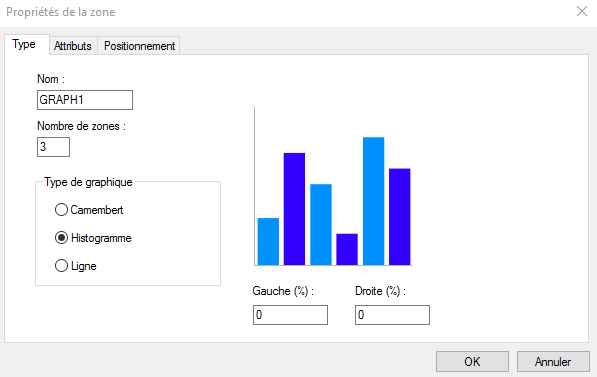
- Type:
- Name of the graph: which will be included in the name of the zones,
- Number of zones which will lay out the graph,
- Graph type: Pie, Bar or Line chart
- Type:
NB: For the graph type = Bar chart, it is possible to define the spacing between the bars on the right and on the left (in %). This option can be used, for example, to add spacing between the bars so that a second graph can be overlaid on top of the first one.
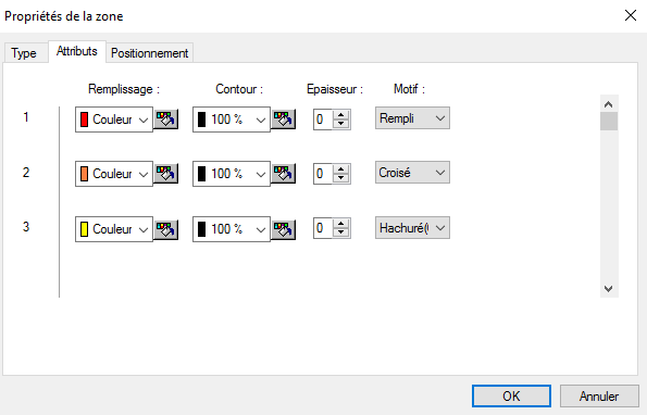
- Properties: allows you to choose the filling, the border, the width of the outline, the filling type, …
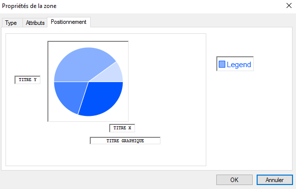
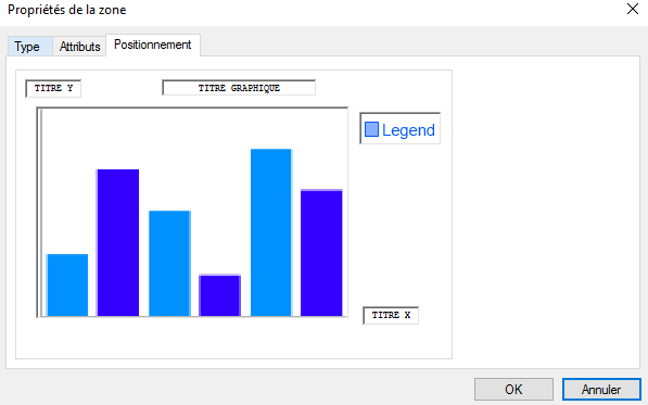
- Positioning: allows you to place the titles (X, Y, of the graph) as well as the legend, to resize the graph according to the preferences of the user.
N.B. The print area of the graph is delimited by the large rectangle, so everything outside this area will not be visible when printing (e.g. the "Legend" area is outside the rectangle in the first image below while it is inside it in the second).
- The Legend is built by selecting zones in the spooled file which will act as legend for the chosen attributes. As with any other data, the zone must be named (e.g. give a name to the graph) and the properties of the zones must be specified with Type = "Graph" and Sub-type = "legend data".
N.B. Be careful to respect the order of the data selection when defining the zones that will be used for the legend because they will follow the same order as that of the attributes.
By creating a group
The principle is the same as that described above except that the data is assembled into a group. This option is possible if the data of the chart follow in the spooled file.
- Create a group that will define the data to be taken into account for the construction of the graph and add the selected zones that contain data, titles, legend …
- Name the zone(s) with the same name as the graph and enter its properties with Type = "Graph" and Sub-type according to the role of the zone (title, data, legend…).
The remainder of the construction of the graph is the same as that described above.
Calculations in a group
To simplify calculations in group and especially the management of "total" and "sub-total", a tool has been integrated within Designer. It allows you to process an input XML file using scripts. These scripts are executed before the application of the template.
Adding calculations into a group through this tool is done using the "addline" script function. This function adds a line to a group specifying a sequence of pairs "field name/value" to add.
In addition, the "character string" type parameters must be surrounded by double quotes and field names in formulas by single quotes.
Syntax:
addline(name of the group, name of the line, page break type line, name of the first field, value of the first field, pre-calculation of the first field, name of the second field, value of the second field, pre-calculation of the second field, etc…);
The addline function starts by the following arguments:
- Group name: contains the name of the group where the line should be added.
- Line name: Name of the line to add.
Then, it consists of an unlimited sequence of field / value pairs:
- Field name: field name that has the line.
- Field value: field value possessed by the line.
- Pre-calculation: Boolean value (0 or 1, yes or no). If the field has a calculation then this defines when the calculation should be:
- Yes: The calculation is resolved during the script execution, taking into account all the XML values.
- No: The calculation is solved when using the value in a template and therefore only takes into account the values in the current page.
For example, the following script adds a line to the group named "group":
addline("group","line",yes,"field1","value1",no,"field2","value2",no);
<group name="group">
…
<line name="line" pagebreak=”1”>
<field name="field1">value1</field>
<field name="field2">value2</field>
</line>
</group>
If the field value contains a calculation then the syntax is:
SUM('''''operation''''') to calculate a sum over all the groups of lines.
AVG('''''operation''''') to calculate an average over all the groups of lines.
In this example, "operation is a mathematical calculation using field names in lines of the group. Field names must be surrounded by single quotes.
For example:
<group name="invoice">
<line name="item">
<field name="name">item 1</field>
<field name="price">10</field>
<field name="quantity">2</field>
</line>
<line name="item">
<field name="name">item 2</field>
<field name="price">5</field>
<field name="quantity">3</field>
</line>
<line name="item">
<field name="name">item 3</field>
<field name="price">12</field>
<field name="quantity">4</field>
</line>
<line name="item">
<field name="name">item 4</field>
<field name="price">5.5</field>
<field name="quantity">3</field>
</line>
</group>
To add a total line to this group, this script must be used:
addline("invoice", "LigneTotal",no
"total", "total = SUM('price'*'quantity')", yes
"moyenne", "moyenne = AVG('price'*'quantity')", yes
);
This script adds a total line at the end of the group:
<group name="invoice">
…
<line name="item">
<field name="name">item 4</field>
<field name="price">5.5</field>
<field name="quantity">3</field>
</line>
<line name="LigneTotal">
<field name="total">total = 99.5</field>
<field name="moyenne">moyenne = 24.875</field>
</line>
</group>
Using the Pre-calculation option to "no" allows to not execute calculations when adding the line to the group but when executed by the template. The advantage of this option is to perform calculations only with the written data on the current page, thus allowing the writing of subtotals.
To add a sub-total line to the previous group, use this script:
addline("invoice","LineSubtotal",yes, "subtotal","sous-total = SUM('price'*'quantity')",no);
This script adds a total line at the end of the group:
<group name="invoice">
…
<line name="item">
<field name="name">item 4</field>
<field name="price">5.5</field>
<field name="quantity">3</field>
</line>
<line name="LineSubtotal" pagebreak=”1”>
<field name="subtotal">sous-total = SUM('price'*'quantity')</field>
</line>
</group>
Pagination management
Managing information writing of pagination such as the total number of pages, the number of the batch and the number of pages in the batch is possible in Designer through the following two options:
Batch breaking
The Batch breaking option can be found in the Properties of the template (see 4.2. Creating a project). It defines a Metadata type zone which will be used to group the pages of the final document in batch.
Lors du traitement de la page :
- Si la zone Metadata récupère une nouvelle valeur alors un nouveau lot sera créé. La page en cours appartiendra à ce nouveau lot.
- Si la zone Metadata récupère une valeur déjà récupérée précédemment, la page en cours sera déplacée vers le lot correspondant à cette valeur.
- Si aucune valeur n’est récupérée par la zone Metadata, la page reste dans le même lot que la page précédente.
C’est le système de multi-document du XPS qui est utilisé pour représenter les lots, le fichier de sortie est donc trié par lot (d’abord les pages du premier lot puis les pages du second, etc…).
Variables de remplacement
Pour permettre l’écriture des informations de pagination, il existe des variables de type « post-traitement », c’est-à-dire qu’elles ne seront remplacées par leur véritable valeur qu’au moment de l’impression.
Ces variables, qui peuvent être utilisées dans des zones ou dans des blocs de texte, sont les suivantes :
MAP_TOTAL_PAGE = nombre total de page.
MAP_TOTAL_DOC = nombre total de lot.
MAP_TOTAL_PAGE_IN_DOC = nombre de page dans le lot en cours.
La syntaxe d’utilisation est la suivante :
PST:'''''nom de la variable''''';'''''valeur par défaut'''''
La « valeur par défaut » est obligatoire et permet d’avoir un texte présent dans la page. Ce texte temporaire sera, par la suite, remplacé par sa vraie valeur. Il est important car c’est grâce à ce texte que les calculs de positionnement se feront. Ce texte doit donc posséder un nombre de caractère au moins égal à la valeur maximale attendue par la variable utilisée.
Par exemple :
Affichera "000" dans la page, mais au moment de l’impression cette valeur sera remplacée par :
- " 5" s’il y 5 pages au total.
- " 10" s’il y 10 pages au total.
- "150" s’il y 150 pages au total.
D’autre syntaxes existent aussi, accessibles quant à elles pendant le traitement de la page :
VAR:MAP_CURRENT_PAGE = numéro de la page en cours.
VAR:MAP_CURRENT_DOC = numéro du lot en cours (la zone Metadata gérant la rupture de lot doit être définie avant l’utilisation de cette variable).
VAR:MAP_CURRENT_PAGE_IN_DOC = numéro de la page en cours dans le lot en cours.
Et de manière générale :
VAR:variable d’env = récupère le contenu de la variable d’environnement.
Gestion des veuves et orphelines
Une gestion complexe des veuves et orphelines est possible grâce à deux fonctionnalités : Groupe entier et Répéter un groupe XML.
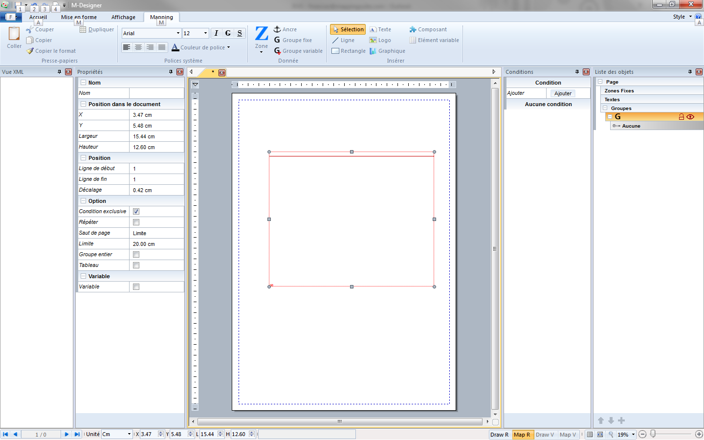
Groupe entier
Lorsqu’on utilise une génération de saut de page de type Limite, une nouvelle option apparait dans les Propriétés du groupe : Groupe entier. Cette option permet d’indiquer que le groupe ne peut pas être coupé et qu’il doit donc s’imprimer intégralement sur une seule page. Si la limite déclenche un saut de page, aucune ligne du groupe ne sera imprimée, le groupe sera entièrement traité sur la page suivante.
Répétition de groupe XML
La répétition de groupe XML part du principe que le groupe apparait plusieurs fois dans le fichier XML d’entrée. Cette fonctionnalité s’active avec le paramètre « Répéter » dans les propriétés du groupe.
Exemple :
Dans l’exemple ci-dessous, le groupe “invoice” apparait trois fois dans le XML. Par défaut, le groupe de la maquette ne pourra récupérer que les informations de la première apparition du groupe dans le XML. Mais si l’option « Répéter » est cochée, l’exécution du groupe se poursuivra sur toutes les apparitions.
<group name="invoice">
<line name="item">
<field name="name">item 1</field>
<field name="price">10</field>
<field name="quantity">2</field>
</line>
<line name="description">
<field name="description">Description item 1</field>
</line>
</group>
<group name="invoice">
<line name="item">
<field name="name">item 2</field>
<field name="price">5</field>
<field name="quantity">3</field>
</line>
<line name="description">
<field name="description">Description item 2</field>
</line>
</group>
<group name="invoice">
<line name="item">
<field name="name">item 3</field>
<field name="price">12</field>
<field name="quantity">4</field>
</line>
<line name="description">
<field name="description">Description item 3</field>
</line>
</group>
L’utilisation conjointe d’une limite générant des sauts de page avec l’option “Groupe entier” et la répétition active permet de gérer un système complexe de veuves et orphelines.
Dans notre exemple, les lignes « item » et les lignes « description » ne pourront pas être séparées par un saut de page.


