ONYX - 9.0 - Usage
Using ONYX Server
Sommaire
- 1 ONYX Server: General principles
- 2 Development Menus
- 3 Administration Menu
- 4 Operations Menu
- 5 ONYX Server maintenance
ONYX Server: General principles
Software
ONYX Server is the production engine of the Mapping Suite on Linux and Windows. Apart from their specific features (file system, user rights management), the philosophy, configuration, the way the engine works and is used are identical on both platforms.
The ONYX Server engine mainly relies on its job manager (called Spooler or Output Manager), a scheduler which processes, prints and distributes documents, from their input into the engine to their output towards the end users. Combined with the Mapping Spooler, the Workflows engine allows you to automate the entire output production chain as well as all the processings to run on documents: data extraction, graphical formatting and mapping, indexing, sorting / splitting, routing, omnichannel distribution, etc.
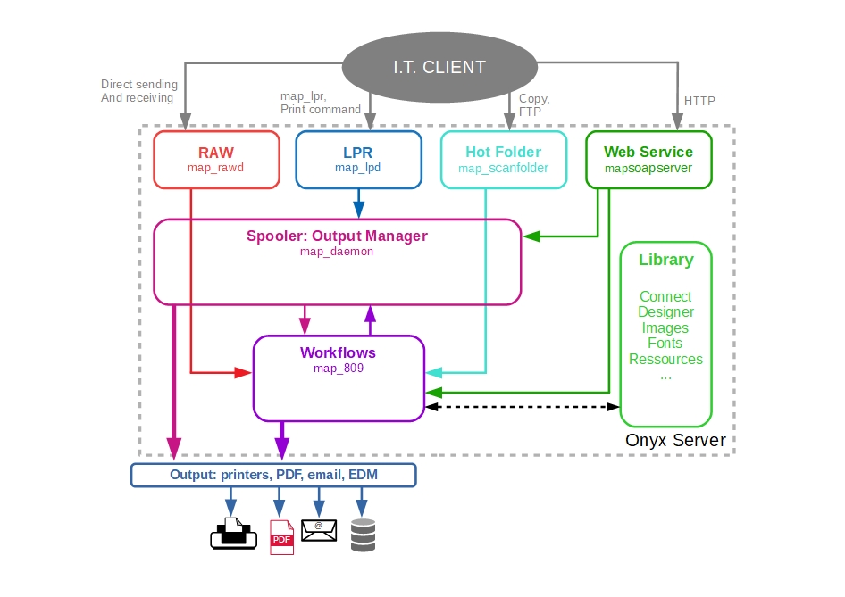
Diagram of the general operations
ONYX Server manages the entire output production chain of the company. The Spooler (or Output manager) and the Workflows engine constitute the nerve center of the solution. They centralise and schedule every query coming from various sources and are subject to multiple protocols (LPR, RAW, FTP/SFTP, Web Service), they apply processing, mapping, routing, and omnichannel distributing rules to them.
Administration / Operations interface
If the ONYX Server is a fat client installed on the target platform, its administration and operation tasks can be carried out remotely via web browser (minimum Internet Explorer 8.0, Firefox, Google Chrome). This thin client access is supported by the Apache HTTP Server software which is the only software required to install ONYX Server.
Access, logging in
To access the ONYX Server Web interface, the DNS name or IP address of the server as well as the HTTP port used for Mapping (8002 on a "Typical" installation) must be known. The adress which needs to be typed in your browser uses this syntax: http://192.168.216.29:8002
Access to the ONYX Server Web interface is controlled and secured. Although it is possible to interface ONYX Server with an Active Directory service or an existing LDAP, the first login to the interface is done through the Apache server, with the admin account of the solution which was specified upon installation of the software, that is to say "mapadmin" by default:
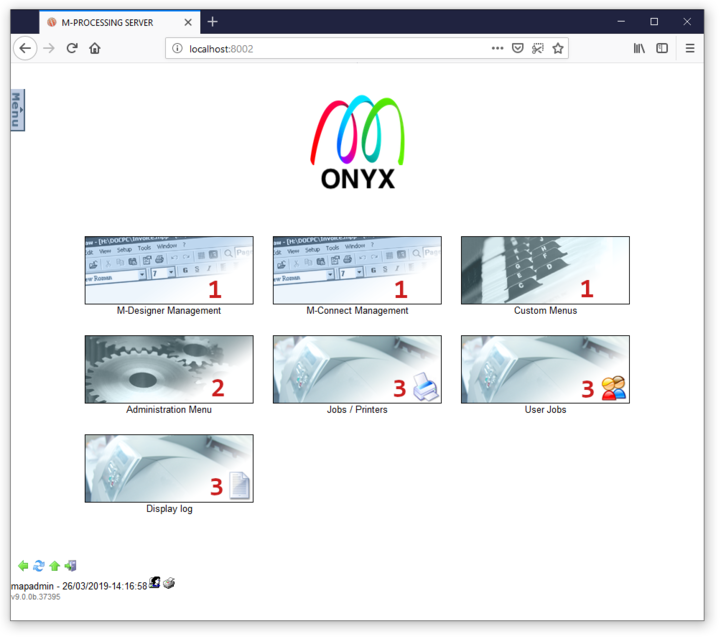
Home page
Once logged in, the ONYX Server home page offers access to different menus:
- Development Menu (1): Manages M-Connect and M-Designer formats, gives access to customised menus to go along with M-Connect formats
- Administration Menu (2): Manages the overall configuration of the solution, manages access rights, creates entry points, managing rules (Workflows), output printers and document distribution rules, manages roll-outs between ONYX Server servers
- Operations Menu (3): Manages jobs, queues, access to event logs
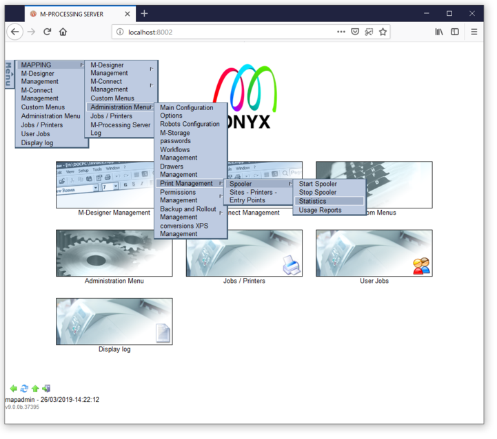
A drop-down menu provides quick access to the entire menu tree-structure at any time during navigation:
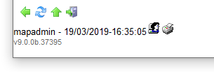
Lastly, At the bottom of the screen, on the left, in addition to session information (logged in user, date and time) and the version number of ONYX Server, a navigation bar allows you to:
- Come back to the previous menu (integrated management of the navigation history, unlike the "Previous" button of your browser)
- Refresh the current page
- Come back to the main menu
- Log off
Development Menus
The first three menus of the user interface are called "Development" screens, they allows you to manage document template libraries which were created with the Connect and Designer tools.
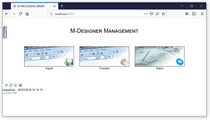
Managing Designer
The different screens respectively allow you to:
- Import Designer formats which were generated from the tool, so that they can be available to and used by the processing rules of the ONYX Server engine
- View and reinitiate the List of Objects and resources used in Designer formats which can be seen in the server (imported or not)
- View the list of Designer Formats in production on the server, you can delete each format from the server or roll them out to another ONYX Server environment.
- Declare, configure and manage the different Conversion Rates which can be used in Designer formats.
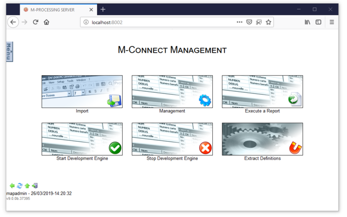
Managing Connect
The different screens respectively allow you to:
- Import Connect formats which were generated from the tool, so that they can be available to and used by the processing rules of the ONYX Server engine
- Manage and view the list of Connect formats in production on the server, you can delete each format from the server or roll them out to another ONYX Server environment.
- Execute a Connect format in interactive mode, so that, for instance, you can confirm that the server is running smoothly
- Start and Stop the Connect development engine on the server which allows users to create previews.
- Retrieve the definitions of databases tables which were interfaced with the Connect tool, the resulting files are then imported into the tool to create the internal structure of data in the developed Connect formats.
Customised Menus
This screen gives you access to interactive interfaces which allow you to execute Connect formats upon request, to create output production queries. These interfaces are developed from the Connect tool, generated and imported with the corresponding format(s), and can answer to a need of production upon request, they, however, cannot be automated.
Administration Menu
This menu gives access to the configuration of the solution, the creation and administration of ONYX Server entry points (Scanfolder robots, listening servers, processing queues), execution and routing rules (Workflows), output points and distribution of documents.
The main screens are the only ones regarded in this documentation, for more information see the User Guide of the solution.
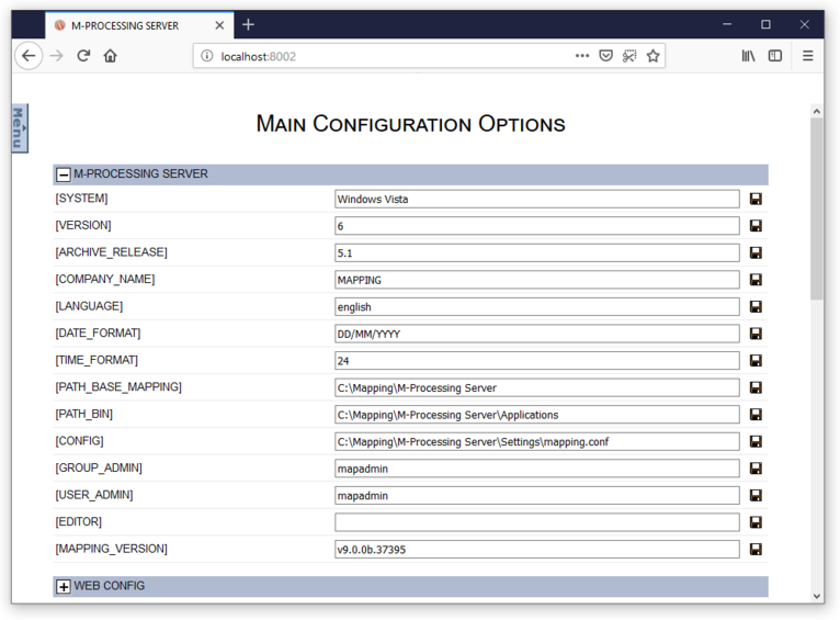
Managing the configuration
This screen displays all the environment parameters of the solution from its installation to its general configuration.
Most values featured here are only informative and must not be changed unless explicitly requested. The User guide of the solution provides more information on values which can be changed as well as their behaviour depending on the context of the application.
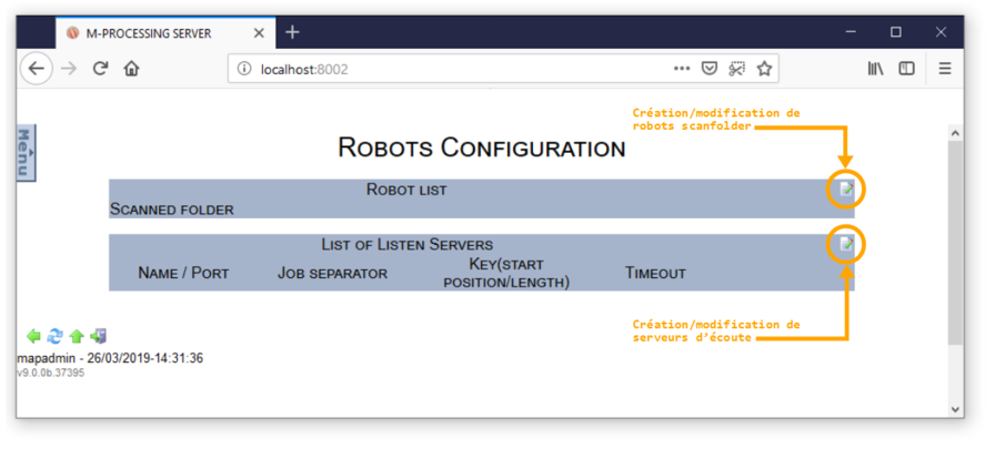
Managing robots
This screen can manage all the "robots" configured in the solution, whether they are Scanfolder robots or listening Servers. Upon first installation, the list of robots is blank but it gives access to the creation / editing screen for new entry points in ONYX Server:
From the perspective of ONYX Server, a robot is an entry point into the solution, a way for a third party application to send an execution query. Robots are programs executed as background tasks (in Service mode under Windows) to monitor data delivery: in a folder in the case of Scanfolder robots, on a network port in the case of listening servers. Each file received is handled by the Workflow execution engine, to then carry out the appropriate processing.
Scanfolder Robots
Introduction
- Scanfolder robots monitor a file system folder searching for input files (transferred by copy or FTP/SFTP). Files detected in the folder are sent one by one to the execution engine to be processed according to the rules defined in the Workflows.
- A robot which was configured in ONYX Server can only monitor one file, the same way a folder of the file system can only be monitored by one Scanfolder robot. There can be as many scanfolder robots created and configured as there are folders to monitor. Each robot is independent from the others, so several files can be processed by different robots at the same time.
Creating / Editing / Deleting
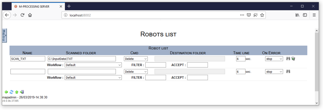
This screen gives you access to the list of robots which are already configured, each robot can be edited if necessary (and if it is not currently running). The last block which contains two blank lines allows you to create a new Scanfolder robot:
Parameters to specify to configure the robot:
Name: gives a name to the robot.
- This parameter is optional, but it is highly recommended: the name of each robot is an environment variable which is accessible and can be used in Workflows.
- ONYX Server checks that the names used for the different robots are unique.
* Folder to scan: Complete path of the folder scanned by the robot.
- This parameter is required.
- It can point to a network drive or a UNC path (under Windows), in this case be careful to have access rights.
- ONYX Server checks that the names of the folders monitored by the different robots are unique.
- ONYX Server can create the folder specified if it does not already exist.
* CMD: action run on every detected file after it was properly processed by the execution engine.
- This parameter is required.
- Delete: Files which were detected and processed are deleted from the monitored folder.
- Move: Files which were detected and processed are moved to another folder, for the history for instance.
* Destination folder: destination path of processed files.
- This parameter is required if the move command was previously chosen.
- ONYX Server checks that the destination folder is different from the monitored folder.
- ONYX Server can create the folder specified if it does not already exist.
* Delay: waiting time interval in between two folder scans, given in seconds.
- This parameter is required.
* On Error: defines the robot's behaviour when a processing error is reported on a detected file.
- This parameter is required.
- Stop: the robot stops, the file in error status stays in the monitored folder.
- Continue: the robot continues to process the next files, the file in error status stays in the monitored folder, renamed with the suffix " _FAILED " (Mapping keyword to prevent the robot from processing this file again during the next folder scan).
- Retry: the robot continues to process the next files, the file in error status stays in the monitored folder. The robot will try to process the file again next time it scans the folder.
Workflow: name of the Workflow to execute.
- This parameter is optional. If not specified the root Workflow is executed by default.
Filter: excludes files from being scanned by the robot.
- This parameter is optional.
- Example: *.tmp files in the monitored folder are not processed by the robot.
Accept: limits the type of files to process.
- This parameter is optional.
- Example: only *.xml files in the monitored folder are processed by the robot.
To create a new robot, specify all the parameters needed then click on the ![]() button to add the robot to the server configuration.
button to add the robot to the server configuration.
To edit an existing robot, edit it or the parameters concerned then click on the ![]() button to edit the robot in the server configuration.
button to edit the robot in the server configuration.
Note: A robot must be stopped for you to edit it.
To delete an existing robot, click on the ![]() button. The robot will be deleted from the server configuration.
button. The robot will be deleted from the server configuration.
Note: A robot must be stopped for you to delete it.
Usage
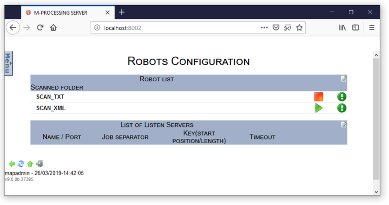
Once the robots created and configured, they appear on the managing screen:
This screen allows you to:
Once started, a robot is a process which is continuously executed as a background task. The ONYX Server binary which is associated with it is map_scanfolder, the list of active system processes (Task Manager under Windows, ps –ef command under Unix) will display as many map_scanfolder[.exe] processes as there are robots started.
Note:
Under Windows, robots are installed as Services in the Windows Service Manager. This is registered the first time the robot is started. The corresponding Service is named based on the name of the robot if specified (which is why the names of the robot must be different) in the monitored folder (which is why the names of the folders must be different). Example: Mapping_ScanFolder_SCAN_TXT.
Each Windows Service created by the robot is configured in manual start by default, this can be switched to an automatic system start afterwards.
Temporary files associated with the robots:
Once started, each robot creates two files in the ONYX Server temporary folder. The first one is named based on the name of the monitored folder, special characters are replaced with ‘_’, and the suffix " map_scanfolder.ID " is added. Example: E__InputData_TXT_map_scanfolder.ID
The second one is named with the system number of the associated process map_scanfloder[.exe]. Example: 75668.pid.
These files are intended for internal use of the process only and will be deleted once the robot is stopped.
However, the Web interface relies on these files to indicate the status of the robots.
Useful command lines:
- To start a robot:
Linux (after the environment was loaded):
/apps/mapping/bin/map_scanfolder -name:SCAN_TXT
Windows:
E:\MappingWindows\Applications\map_scanfolder.exe -name:SCAN_TXT
- To stop a robot:
Linux (after the environment was loaded):
/apps/mapping/bin/map_scanfolder -name:SCAN_TXT -stop
Windows:
E:\MappingWindows\Applications\map_scanfolder.exe -name:SCAN_TXT -stop
- If the robot is not named, set each parameter that describes the robot as an argument of the previous commands (hence the prior advice on robots unique names)
Listening Servers
Introduction
- A listening server monitors a network port, searching for received data (data is sent via a remote system by direct transfer in RAW protocol). The robot receives data and builds files locally, it then sends them one by one to the execution engine to be processed according to the rules defined in the Workflows.
- A robot configured in ONYX Server can only monitor one network port, and a network port can only be monitored by one listening server. There can be as many listening servers created and configured, as there are ports to monitor. Each robot is independent from the others, so several files can be processed by different robots at the same time.
Creating / Editing / Deleting
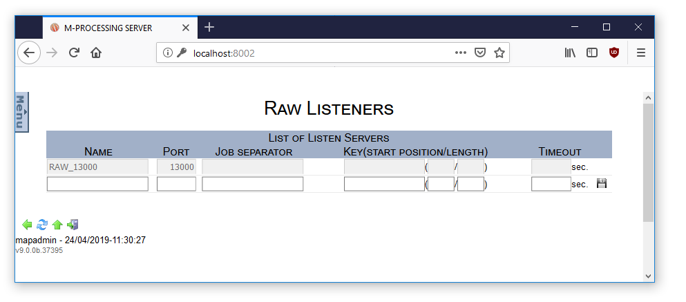
The following screen displays the list of robots which are already configured, each robot can be edited if necessary (if it's not currently being run). The last blank line allows you to create a new listening server:
Parameters to specify to configure a listening server:
Name: gives a name to the robot.
- This parameter is optional, but it is highly recommended: the name of each robot is an environment variable which can be accessed and used by the Workflows.
- ONYX Server checks that the names used for the different robots are unique.
* Port: number of the network port the robot listens to.
- This parameter is required.
- ONYX Server checks that the names of the ports the different robots listen to are unique.
Job separator: character or chain which divides a large network stream into several files.
- This parameter is optional.
Key (start/length): adds information to the name of the temporary file built by the robot.
- These 3 parameters are optional.
- The information is searched in the network stream, using a keyword, ignoring X characters after the keyword ("start" parameter), retrieving N characters ("length" parameter).
- This information can be used in the Workflows, notably as a condition.
Timeout: network waiting time, given in seconds.
- This parameter is optional.
- Prevents the network port from being blocked in case of problem with the stream transmitter: the robot cuts connection after this inactivity period, as it considers the established connection is no longer active.
To create a new listening server, fill in all the needed parameters, then, click on the ![]() button to add it to the server configuration.
button to add it to the server configuration.
To change an existing server, edit it or its parameters, then, click on the ![]() button to edit the server configuration.
button to edit the server configuration.
Note: The server must be stopped for you to change it.
To delete an existing listening server, click on the ![]() button. The robot is then deleted from the server configuration.
button. The robot is then deleted from the server configuration.
Note: The robot must be stopped for you to delete it.
Usage
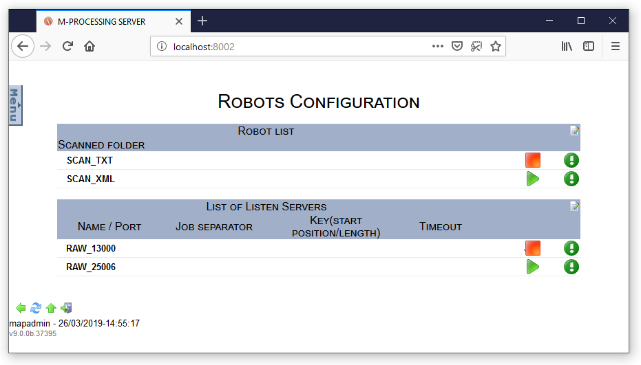
Once created and configured, the robots appear on the managing screen:
This screen allows you to:
Once started, a listening server is a process which is continuously executed as a background task. The associated ONYX Server binary is map_rawd, the list of active system processes (Task Manager under Windows, ps –ef command under Unix) will display as many map_rawd[.exe] processes as there are listening servers started.
Note:
Under Windows, listening servers are installed as Services in the Windows Service Manager. This is registered the first time the robot is started. The corresponding Service is named base on the name of the network port the robot listens to (which is why the names of the ports must be different) in the job separator. Example: Mapping_Rawd_13000, Mapping_Rawd_25006_SEP.
Each Windows Service created by the robot is configured in manual start by default, this can be switched to an automatic system start afterwards.
Temporary files associated with the listenign servers
Once started, each listening server creates a file in the ONYX Server temporary folder. It is named based on the name of the network port it listens to as well as the name of the job separator, with a map_rawd.ID file which includes the number of the associated process. Example: …\Temp\map_rawd_25006_SEP\map_rawd.ID.
Useful command lines:
- To start a robot:
Linux (after the environment was loaded):
/apps/mapping/bin/map_rawd -start -name:RAW_25006
Windows:
E:\MappingWindows\Applications\map_rawd.exe -start -name:RAW_25006
- To stop a robot:
Linux (after the environment was loaded):
/apps/mapping/bin/map_rawd -stop -name:RAW_25006
Windows:
E:\MappingWindows\Applications\map_rawd.exe -stop -name:RAW_25006
- If the robot is not named, set each parameter that describes the robot (listening port and job separator) as an argument of the previous commands (hence the prior advice on robots unique names)
Managing the Spooler
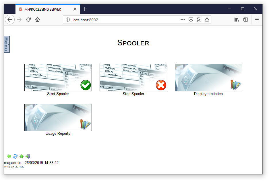
As mentioned previously, the Onyx Server Spooler is the heart of the solution. It is a real stream, processing and printer manager. The interface displayed when navigating through the Administration Menu, to Managing print jobs, and finally Managing the Spooler, allows you to:
- Start the Spooler
- Stop the Spooler
- See output production statistics
- See solution usage reports
Once started, the Spooler is a process which is continuously executed as a background task. The associated Onyx Server binary is map_daemon[.exe].
Note:
Under Windows, the Spooler is installed as a Service in the Windows Service Manager. This is registered the first time the Spooler is started. The corresponding Service is named Mapping_Spooler. It is configured in manual start by default, but this can be switched to an automatic system start afterwards.
Temporary files associated with the Spooler:
Once started, the Spooler creates a "map_daemon.ID" file in in its OnyxServer installation folder: C:\ProgramData\MappingWindows\Spooler by default under Windows, /apps/mapping/spool by default under Linux.
Useful command lines:
- To start the Spooler:
Linux (after the environment was loaded):
/apps/mapping/bin/map_daemon start
Windows:
E:\MappingWindows\Applications\map_daemon.exe start
- To stop the Spooler:
Linux (after the environment was loaded):
/apps/mapping/bin/map_daemon stop
Windows:
E:\MappingWindows\Applications\map_daemon.exe stop
Managing Sites and Queues
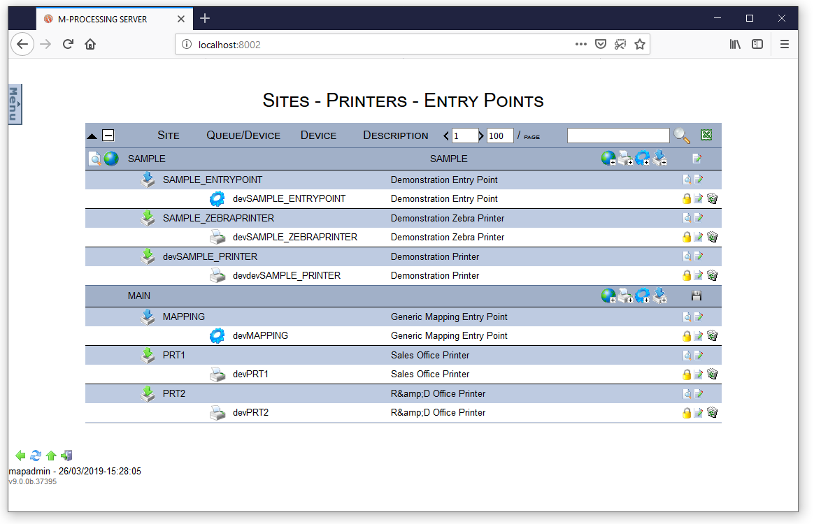
The interface displayed when navigating through the Administration Menu, to Managing print jobs, and finally Managing Queues / Devices / Input, gives you access to the list of all queues configured in the Spooler, potentially being organised per site:
Here for example, a "SAMPLE" site was declared in which 3 queues (one input queue and two output queues) are configured. 3 other queues are declared outside of sites and displayed in a default site called Main.
Using this interface, inside each site, you can:
![]() Create a site. Sites are a logical way of organising queues
Create a site. Sites are a logical way of organising queues
![]() Create an output queue linked to a physical printer
Create an output queue linked to a physical printer
![]() Create a customised processing queue which executes a client queue (shell)
Create a customised processing queue which executes a client queue (shell)
![]() Create a Mapping processing queue which executes a Workflow
Create a Mapping processing queue which executes a Workflow
Important notes:
All the created and configured objects must have a unique name no matter their type (an output printer must not have the same name as a site).
Once created and configured, the name of an object cannot be changed anymore. If necessary, the object must be deleted and then recreated.
Creating a site
Sites allow you to classify Spooler queues so that print jobs can be managed within a hierarchical way. Sites can also be used as display filters or search filters in the operations view.
To create a site, click on the ![]() button.
button.
Note:
It is possible to create sites within a site, this allows you to manage a complex tree view. To do so, use the creation button on the line of the concerned site.
Fill in each of the following information in the input screen and validate it by clicking on ![]() :
:
- (1) Name for the site (required)
- (2) Description
Once the site configuration finished, the new site needs to be saved, click on ![]() (3).
(3).
Creating a (simple) input point
An ONYX Server input point is a queue which executes Mapping processings (Workflows). It is made up of two objects:
- A queue to receive queries (jobs)
- A "device" or engine, to handle queries and carry out processings
To add an input point to a site, click on the ![]() button, on the line of the concerned site.
button, on the line of the concerned site.
The following input screen gives you access to several tabs, the first one is the only one this documentation will detail. Refer to the User Guide for more details on the advanced configuration options.
Fill in the needed information and validate it by clicking on ![]() .
.
Queue
- (1) Name for the queue (required)
- (2) Description for the queue
Validating the name of the queue gives you access to the creation form of the associated device.
Device
- (3) Name for the associated device (required)
- (4) Description for the device
Driver
- (5) Type of driver: RULES by default, this cannot be changed (this is the execution engine which is called)
- (6) Executed Workflow, has to be chosen in the drop down menu. By default (‘Default’ or ‘undefined’), the root Workflow is executed.
Monitoring
- (7) Behaviour of the device upon error:
- default or stop: the current processing stops in error status, the device stops in error status.
- continue: the current processing stops in error status, the device continues to process the next queries.
- ignore: the current processing as considered as done, the device continues to process the next queries. This value is not recommended, except for very specific cases.
- (8) Automatic recovery: if activated, an error inducing processing is relaunched
- Timeout: maximum time during which a processing in error status is relaunched before it is actually considered as being in error status. The behaviour of the device upon error is then taken into account.
Note:
Automatic recovery is not necessarily recommended on input queues. If a Workflow triggers an error, chances are this error will keep happening as long as the Workflow is not fixed.
Once the (simple) configuration of an input point done, the new object needs to be saved, click on ![]() (9).
(9).
Creating a (simple) printer
An ONYX Server printer is a queue which communicates a physical printer. It is made up of two objects:
- A queue which receives queries (jobs)
- A "device" or printer, which handles queries and sends data to the physical printer.
To add a printer to a site, click on the ![]() button on the line of the concerned site.
button on the line of the concerned site.
The following input screens gives you access to several tabs, the first one is the only one this documentation will detail. Refer to the User Guide for more details on the advanced configuration options.
Fill in the needed information and validate it by clicking on ![]() .
.
Queue
- (1) Name for the queue (required)
- (2) Description for the queue
Validating the name of the queue gives you access to the creation form of the associated device.
Device
- (3) Name for the associated device (required)
- (4) Description for the device
- (5) Backup: if activated this allows you to create a backup printer which will automatically replace the main printer in case of error.
Driver
- (6) Connection: Onyx Server implements several types of communication protocols, the LPR protocol is the most used here (refer to the User Guide for more details on the other protocols).
- (7) Print job: "default" indicates a link to a physical printer, "MAPPING" indicates a communication with another (remote) Onyx Server Spooler and allows you to activate the compression of streams.
- (8) XPS compatibility: allows you to communicate with the linked physical printer in its direct printing language. The XPS streams are converted on the fly according to the selected profile then sent to the printer. This operation does not depend on any driver.
- (9) IP address of the physical printer
- (10) Internal name of the physical printer: generally PASS if it is directly linked to the network, or the name of the port on the box (HP JetDirect for instance) is it is used to link the printer to the network.
- (11) Time: maximum waiting time for a network communication.
Status
This allows you to ask the physical printer for its status, which will be displayed in the operations view.
Monitoring
This allows you to ask the physical printer to control the real status of the print job. This additional communication is detailed in the User Guide, the default parameters are enough for the moment.
- (12) Behaviour of the device upon error:
- default or stop: the current processing stops in error status, the device stops in error status.
- continue: the current processing stops in error status, the device continues to process the next queries.
- ignore: the current processing is considered as done, the device continues to process the next queries. This value is not recommended, except for very specific values.
- (13) Automatic recovery: if activated, an error inducing print job is relaunched
- Timeout: maximum time during which the print job in error status is relaunched before it is actually considered as being in error. The behaviour of the device upon error is the n taken into account.
- Recovery mode: in its entirety or per page
Once the (simple) configuration of the printer is finished, the new object needs to be saved, click on ![]() (14).
(14).
Sending a file to a queue
The ONYX Server Spooler is seen as a 'virtual' printer from a third-party application. Print commands are used to send files to a queue of the Spooler.
ONYX Server has its own print commands: map_lp locally and map_lpr remotely.
MAP_LP locally
MAP_LP is a direct query sent to the ONYX Server Spooler (the map_daemon program answers it).
Two parameters are required for this command:
-queue:XXX: the name of the queue in which the file is sent
-data:XXX: the path of the file to send
Other parameters are available for this command (argument --help to access the list of parameters), the most common ones are:
-title:XXX: gives a title to the document in the queue, displayed in the operations view
-user:XXX: defines the username of the document owner in the queue
-map_hold: the file is sent in "hold" status (it will be processed after)
-map_save: saves the file after it was processed
-map_retention:NN: adds a retention time (in days) in the spooled file attributes
Example: the following commands add a spooled file in the INPUT_DATA queue which is owned by the mapadmin user. It has a retention time of 15 days and will appear in saved status once processed.
Under Windows:
E:\MappingWindows\Applications\map_lp "-queue:INPUT_DATA" "-map_hold" "-map_save"
"-map_retention:15" "-user:mapadmin" "-data:D:\Data\extract\FR_DEMO.txt"
Under Linux:
/apps/mapping/bin/map_lp "-queue:INPUT_DATA" "-map_hold" "-map_save" "-map_retention:
15" "-user:mapadmin" "-data:/opt/data/extract/FR_DEMO.txt"
MAP_LPR remotely
MAP_LPR is a standard network print communication. The data sent to Onyx Server via the LPR protocol is received locally by the map_lpd program, the latter then requests for the Spooler to add the document in the correct queue.
Three parameters are required for this command:
-server:NNN.NNN.NNN.NNN: IP address (or DNS name) of the Onyx Server server
-queue:XXX: the name of the queue in which the file is sent
-data:XXX: the path of the file to send
Moreover, depending on the configuration, the LPD listening server of Onyx Server does not necessarily use the 515 port (standard print port, which may already be used by another application). The Mapping network port must be specified with argument -port:NNN in this case.
Other parameters are available for this command (argument --help to access the list of parameters), the most common ones being identical to the map_lp command.
Example: the following commands add a spooled file in the INPUT_DATA queue which is owned by the mapadmin user. It has a retention time of 15 days and will appear in saved status once processed.
Under Windows:
E:\App\Mapping_client\map_lpr -server:192.168.217.57 "-queue:INPUT_DATA" -map_hold -map_save
-map_retention:15 -user:mapadmin  "-data:D:\Data\extract\FR_DEMO.txt"
Under Linux:
/apps/mapping_client/map_lpr -server:192.168.217.57 "-queue:INPUT_DATA" -map_hold -map_save
-map_retention:15 -user:mapadmin  "-data:/opt/data/extract/FR_DEMO.txt"
Managing Workflows
Introduction
Workflows make the ONYX Server execution engine. A Workflow is defined as a set of configurable conditions and commands, executed when a new file is received on an input connector (Scanfolder robot, listening server, input point, or by Web Service request). Commands are processed one by one: the second command is processed after the first one was processed properly, and so on until the end of the Workflow.
A Workflow is defined graphically by linking different types of objects: commands, conditions and parameters. Its name must be unique and it must be linked to at least one connector to be active.
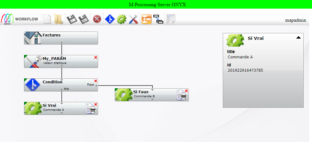
Example of a Workflow:
The following Workflow, which is build later in this guide:
- Defines a parameter by reading information in the input file
- Defines a condition by comparing the value of this parameter with a keyword
- Defines two processings, if the condition is true or false
Workflows are saved on disk in XML files, in the "workflow" sub-folder of the rules folder which is pointed by the RULES_PATH configuration variable.
On the ONYX Server web interface, the administration and configuration of Workflows is accessed through the Administration Menu, Managing Workflows.
Advice: Firefox is recommended as browser for better user experience.
Toolbar
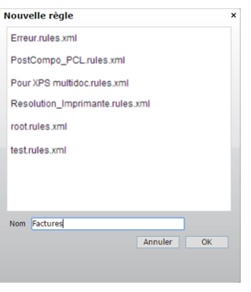
![]() Create a new Workflow. Enter the name of the Workflow, the .rules.xml extension is automatically added.
Create a new Workflow. Enter the name of the Workflow, the .rules.xml extension is automatically added.
![]() Open a Workflow. Select a Workflow in the list.
Open a Workflow. Select a Workflow in the list.
![]() Save the active Workflow under another name.
Save the active Workflow under another name.
![]() Add a condition to the active Workflow. the new condition is added after the selected box.
Add a condition to the active Workflow. the new condition is added after the selected box.
![]() Add a command to the active Workflow. the new command is added after the selected box.
Add a command to the active Workflow. the new command is added after the selected box.
![]() Add a a parameter to the active Workflow. The new parameter is added after the selected box.
Add a a parameter to the active Workflow. The new parameter is added after the selected box.
![]() Redraw the active Workflow. Graphically redraws the Workflow: aligns boxes, links, etc…
Redraw the active Workflow. Graphically redraws the Workflow: aligns boxes, links, etc…
![]() Duplicate an object. Duplicates (name, parameters, etc.) a selected object, without its links.
Duplicate an object. Duplicates (name, parameters, etc.) a selected object, without its links.
![]() Manage resolution tables. Creates, edits and deletes resolution tables
Manage resolution tables. Creates, edits and deletes resolution tables
Creating a new Workflow
Click on the ![]() icon, give a name to the Workflow and validate by clicking on:
icon, give a name to the Workflow and validate by clicking on:
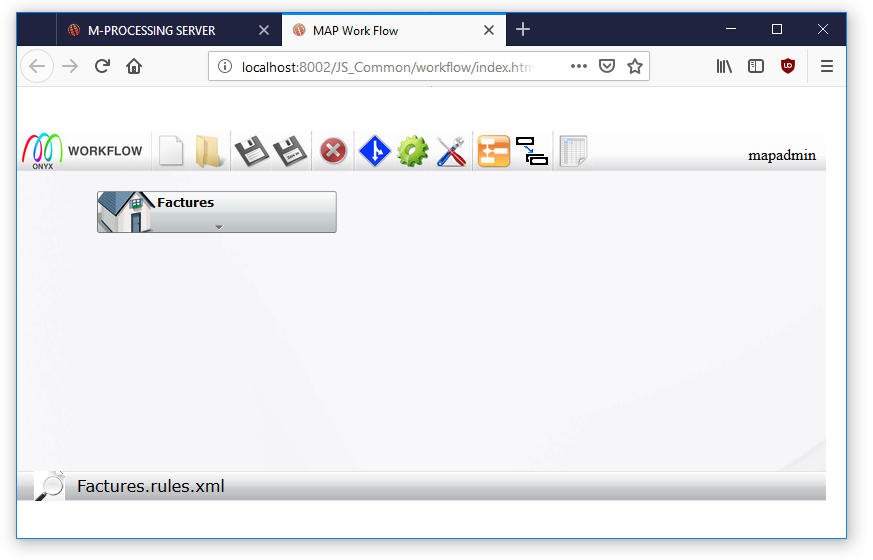
The new Workflow is displayed in the editing window, with a first box, starting point of the processing sequence:
Adding a Parameter
Définition
The parameter objects allow you to define the value of a parameter or to create a new one. A parameter can then be used as a condition or command. This allows you to reuse a value in several commands for instance, without having to define it each time.
Create / Edit
To create a new parameter, select the box after which the new parameter must be added, then, click on the ![]() icon. To edit an existing parameter, double-click on the corresponding box.
icon. To edit an existing parameter, double-click on the corresponding box.
µThe editing window for a parameter opens to define the different fields:
- (1) Name of the parameter to define (required)
- (2) Value to affect (required)
- (3) Title of the object
- (4) Note (blank field for comments)
Note:
A parameter is generally reused afterwards in the Workflow, in a condition or a command, even sometimes in another Workflow. Choosing names that reflect the information transmitted is recommended.
Value
Different methods can be accessed through the context menu to define the value of a parameter in the input field:
- param: dynamic value of a system environment parameter, linked to Onyx Server, the Workflow or the input spooled file
- value: static value entered by the user
- rulefile: dynamic value in a text or an XML file (may be the input spooled file, or any other file)
- command: dynamic value obtained after a predefined Onyx Server command was executed
- cmd: dynamic value obtained after a user script was executed
- SQL: dynamic value obtained after an SQL request (SELECT type in this case) was executed
- resolve: dynamic value obtained after a research in a resolution table
- rulefile_multiple: defines several parameters with a dynamic value at once, with information in the same input file (in XML mode only).
Depending on the type of field needed, predictive text can be used, this option displays a new interface to configure the dynamic recovery of the value:
Every predictive text function and field type is detailed in the Onyx Server User Guide.
Adding a Condition
Definition
Condition objects define 2 different processings depending on the validity of a condition. Condition boxes are the only ones which have two outputs:
- at the bottom (direct path) if the condition is true
- on the right (bypath) if the condition is false
A condition is defined as a comparison between at least 2 values. As seen previously, a value can be a parameter, a constant, the result of a command or a script, of a research in a resolution table, of an SQL query, of a data file analysis.
Create / Edit
To create a new condition, select the box after which the condition needs to be added, then, click on the condition.png icon. To edit an existing condition, double-click on the corresponding box.
The condition editing window opens so as to define the different fields:
- (1) Name of the condition object
- (2) Title of the object
- (3) Tools to define the logic of the condition: adding/deleting a filter, AND and OR logical operators
- (4) Condition filters
- (5) Logical operators between filters
- (6) Note (blank field for comments)
A condition needs to have at least one condition filter.
Tips:
The field "Name of the object" (1) is optional, filling it in is, however, highly recommended. This information appears in the log associated with the Workflow, which allows you to identify the different stages of the Workflow easily.
Examples: "Condition failed" if no name is provided, otherwise "Condition 'Name of the condition' success".
Condition filter
When creating a new condition you are automatically asked to set a first filter. Double-clicking on a condition allows you to edit it:
- (1) Value to compare
- (2) Comparison operator
- (3) Comparison value
The comparison operators available are:
equal to / different from: strict alphanumerical comparison between 2 values
contains / does not contain: alphanumerical research of a value in another value
is empty / is not empty: does the the parameter have a value?
greater than / greater than or equal to: numerical comparison
less than/ less than or equal to: numerical comparison
A condition can be defined by multiple condition filters. The ![]() button allows you to add a new condition filter. The logic between these filters is defined graphically using the boxes to tick before each filter and the
button allows you to add a new condition filter. The logic between these filters is defined graphically using the boxes to tick before each filter and the ![]() and
and ![]() tools. In this example, the condition logic is defined by: filter A and (filter B or filter C). The
tools. In this example, the condition logic is defined by: filter A and (filter B or filter C). The ![]() button allows you to delete a selected condition filter, or a selected condition logic (and the associated filters).
button allows you to delete a selected condition filter, or a selected condition logic (and the associated filters).
Adding a Command
Definition
Commands allow you to run unitary processings. The Workflow includes as many commands as there are processings to run.
Commands allow you to run the 4 main groups of processings: predefined Onyx Server commands in direct language, user scripts, SQL queries, or calls to other Workflows.
Create / Edit
To create a new command, select the box after which the command needs to be added, then, click on the ![]() icon. To edit an existing command, double-click on the corresponding box. The command editing window opens so as to define the different fields:
icon. To edit an existing command, double-click on the corresponding box. The command editing window opens so as to define the different fields:
- (1) Type of processing: Command, Cmd, Sql or Call
- (2) Name of the object
- (3) Title of the object
- (4) Selector of a group of predefined commands
- (5) Selector of the predefined command to run
- (6) Parameters of the command:
- Displays all the required or optional parameters for the command to be run smoothly
- The Standard tab includes the main parameters of the command
- Depending on the commands, other specific tabs display advanced parameters
- (7) Note (blank fields for comments)
Predefined commands (Command)
This group of processings includes the "generic" commands and ONYX Server direct language commands. Commands are sorted by groups according to what they are used for: Spooler, File, Mapping, XPS Toolbox, Mail…
Amongst the most used ones are:
Mapping / Text M-Designer: application of a Designer format on a data file in text mode
- Standard:
Name of the Designer format to use. The list of formats imported on the server can be seen by clicking on the
 button
Sequence number (00010, or *MRG, or *ALL, etc.)
Input file (data file)
Output file (finished XPS document)
- Advanced:
Translation language (See the Designer User Guide for translations)
XPS file to add as watermark, indexes can also be recovered
- Text options:
Maximum number of lines: an overflow can be set on the input data file, an "automatic" page break can also be set.
Page width: maximum number of characters per ligne to read in the input data file
Code page of the input file: converts to Unicode UTF-16 on the fly if needed. The list of code pages managed under ONYX Server can be seen by clicking on the
 button
- Output options:
Start page / end page: interval of pages to produce
Input bin / output bin: adds finishing options (PrintTicket) to the XPS document produced to manage printer bins
Spooler / Print: sends a spooled file to the Spooler queue
- Standard:
Name of the destination queue. The list of queues declared in the Spooler can be seen by clicking on the
 button
Name of the file to send
Title: name of the spooled file in the queue
Send the spooled file to the destination queue in hold status
Keep the spooled file after it was processed in the destination queue
Keep the following attributes: associate the attributes of the current spooled file with the output spooled file
Add common parameters: associate the parameters of the current session with the output spooled file
- Page:
Start page / end page: adds the corresponding attribute to the destination spooled file for its processing interval
Number of copies: adds the corresponding attribute to the destination spooled file
- Security:
Owner of the destination spooled file
Access rights on the destination spooled file
Account code: associates the corresponding attribute
- Userdata:
Additional attributes can be defined on the destination spooled file
- Advanced:
Priority of the destination spooled file
Number of days during which the destination spooled file is stored
Number of days before the destination spooled file is compressed (this attribute is inherited from the IBM i environment, it is sometimes used by client applications upstream and downstream)
Type of paper
Loyalty: this attribute is inherited from the IBM i environment, it is sometimes used by client applications upstream and downstream
Name of the destination spooled file
The complete list of ONYX Server predefined commands is detailed in the User Guide.
User scripts (Cmd)
The CMD mode allows you to put the command object in text editing mode so as to type a complete command in, as would be done in telnet mode or in MS-DOS command windows. All environment parameters (system and Mapping) and attributes of the file being processed are accessible.
The command being run can be a specific Onyx Server command, which is not available as a predefined command, or a complex script (*.bat or *.sh).
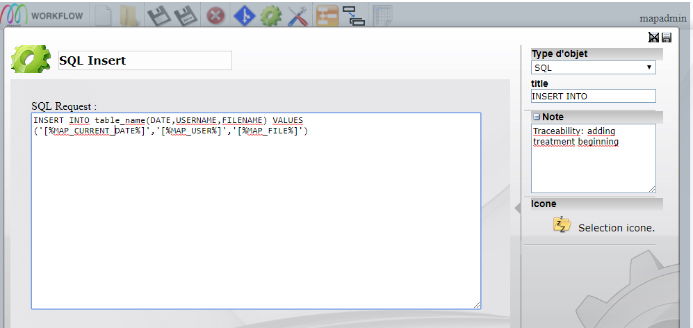
SQL queries
The SQL mode allows you to put the command object in text editing mode so as to run SQL orders. All environment parameters (system and Mapping) and attributes of the file being processed are accessible. Parameters to connect to the database must be defined in the Onyx Server configuration.
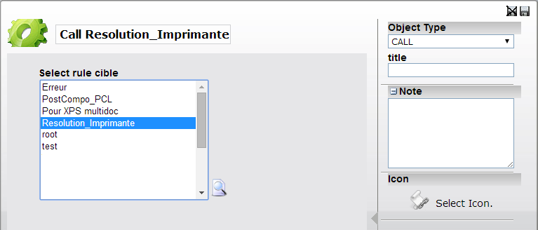
Workflows calls (Call)
The CALL mode allows you to run another Workflow in the current workflow, then to continue running the current Workflow once the second one has been correctly processed. All environment parameters (system and Mapping) and attributes of the file being processed are automatically transmitted to the sub-Workflow and can be used in it.
Operations Menu
The last two menus of the home page give you access to the two most used operations screens of the solution: the jobs and printers managing screen (content of the Spooler), and the screen to access all the logs of the solution.
Jobs/ Printers
This first view gives you access to two tabs:
- The jobs view, which lists all the jobs in the Spooler, in their respective queue
- The "printers" view, which lists all the queues declared in the Spooler, in their respective sites.
Managing Jobs
Navigating through the "Jobs / Printers" menu gives you directly access to the Spooler jobs view:
This view is divided in 3 parts:
- The jobs view and the printers view tabs
Note:
When accessing this first view, the page is automatically refreshed with the default filters. The LOAD_SPOOLS_ON_VIEW (on/off) environment variable allows you to deactivate this refresh so that the user can specify filters.
The view is not refreshed automatically when changing from one tab to another so that the user can specify display filters before the results are refreshed
- A display filter banner, which allows you to limit the number of results or to make a research for a specific element.
Note:
Filters are specified by default as this first view is displayed: on the jobs owner (logged-in user), on dates (one-day history). The filters can be edited, the "Refresh" button refreshes the list of the results according to the specified filters.
- The list of results: all jobs corresponding to the different specified filters, grouped together by site, queue and status. Jobs are displayed in display groups according to their priority level, then, time of input in the queue.
The following actions can be carried out for each job:
![]() Put the job on hold. Jobs with the statuses kept, in error or ongoing processing can be put on hold.
Put the job on hold. Jobs with the statuses kept, in error or ongoing processing can be put on hold.
![]() Release the job. Jobs on hold, kept or in error status can be released.
Release the job. Jobs on hold, kept or in error status can be released.
![]() Transfer the job in another queue.
Transfer the job in another queue.
![]() Print the job using the Web (only under Windows, this allows you to send the job on a printer declared in the Windows Spooler of the workstation).
Print the job using the Web (only under Windows, this allows you to send the job on a printer declared in the Windows Spooler of the workstation).
![]() Recover pages (this allows you to reprint the job from page 5 to 12 for instance).
Recover pages (this allows you to reprint the job from page 5 to 12 for instance).
Managing printers
In this previous view, only the queue which contain jobs are displayed in the results. The "Printers" tab lists all the queues declared in the Spooler:
This view follows the same parting principle as it is divided in three parts:
- The navigation tabs
- The filter banner
- The list of results.
The following actions can be carried out for each job:
![]() Start a queue (or device). Queues that are on hold can be started.
Start a queue (or device). Queues that are on hold can be started.
![]() Stop a queue (or device). Queues that are started can be stopped.
Stop a queue (or device). Queues that are started can be stopped.
![]() Display the configuration information of the queue (or device).
Display the configuration information of the queue (or device).
![]() See the jobs in a queue. This redirects to the "jobs" tab, with a filter activated on the queue.
See the jobs in a queue. This redirects to the "jobs" tab, with a filter activated on the queue.
![]() Refresh device status (if polling is set up in the device configuration).
Refresh device status (if polling is set up in the device configuration).
![]() Reboot the device: restarts a device in error status.
Reboot the device: restarts a device in error status.
See the log
This screen allows you to see all the logs of the Onyx Server solution:
Each process or object has a log:
- The Spooler (map_daemon.log)
- The LPD listening server (map_lpd.log)
- The listening process for Web Service queries (mapsoapserver.log)
- The Scanfolder robots (scan_folder_XXX.log)
- The Rawd listening servers (map_rawd_XXX.log)
- The queues (INPUT_DAT.log for instance)
Each log can be:
![]() Accessed (by clicking on the name of the log)
Accessed (by clicking on the name of the log)
![]() Converted to text to be displayed in a text editor
Converted to text to be displayed in a text editor
![]() Cleared: The log still exists but it content is cleared out
Cleared: The log still exists but it content is cleared out
Example of the content of a print queue log:
The three types of events reported here are:
- OK (success): Print command launched (LPR communication with the physical printer, initiated by the map_lpr command)
- EE (error): Connection error to the printer: the time specified in the configuration of the queue is reached before the connection is established (most probable reason: the physical printer is turned off, or disconnected from the network)
- WW (information): the behaviour of the queue upon error is taken into account
The filter banner on these screens allows you to refine the results:
- Level: only displays error events for example
- Dates: displays all the events from a specific time interval
- Filter: research of a word or expression in the messages associated with the events
ONYX Server maintenance
This section deals with the regular maintenance tasks that must be scheduled in order to maintain optimal performances of the ONYX Server environment.
The following commands can be gathered together in an overall clearing script, which can be scheduled to run automatically on the server:
- Scheduled tasks manager under Windows
- CRONTAB under Linux
Clearing Spooler files
The Spooler normally creates and keeps a certain number of files which we advise you regularly clear: kept jobs, logs, statistics. This can be done using an ONYX Server command: map_cron.
Clearing jobs
All the jobs in the Spooler have a specific attribute: the retention time (in days). The solution uses this attribute to clear the "expired" jobs in the Spooler, in other words, those with an exceeded retention time.
There are two ONYX Server commands which serve this purpose:
- Deleting all the jobs kept (which were processed and kept) with an expired retention time:
Linux: /apps/mapping/bin/map_cron -date
Windows: E:\MappingWindows\Applications\map_cron.exe -date
- Deleting all the jobs (whatever status) with an expired retention time:
Linux: /apps/mapping/bin/map_cron -dateall
Windows: E:\MappingWindows\Applications\map_cron.exe -dateall
Note:
For them to carried out be correctly, these commands must be run as the Spooler is also running. Only the Spooler can interact with its jobs, the previous commands can only send deletion queries to the Spooler.
Clearing logs
The map_cron command clears the files corresponding to ONYX Server logs. Options can be set to keep archives of the logs before they are deleted, to keep history.
- Creating an archive (ZIP) of the logs before deleting them:
Linux: /apps/mapping/bin/map_cron -cleanlog
Windows: E:\MappingWindows\Applications\map_cron.exe -cleanlog
The archive is kept by default at the root of the logs folder (PATH_LOG variable of the configuration) and named according to the date/hour on which the command was run.
Example: 2014_07_25_15_16.zip
- Deleting logs without backup:
Linux: /apps/mapping/bin/map_cron -cleanlog -delete
Windows: E:\MappingWindows\Applications\map_cron.exe -cleanlog -delete
Clearing statistics
Following the same principle as previously, the files corresponding to statistics and usage reports can be cleared:
Linux: /apps/mapping/bin/map_cron -cleanstats [ -delete ]
Windows: E:\MappingWindows\Applications\map_cron.exe -cleanstats [ -delete ]
Clearing temporary files
A certain number of files are normally created in the ONYX Server temporary folder (PATH_TEMP variable in the configuration): connection files to the Web interface (cookies), files derived from Workflow processings, etc.
The map_cron command deletes all cookie files as it only keeps a one-day history:
Linux: /apps/mapping/bin/map_cron -cleanid
Windows: E:\MappingWindows\Applications\map_cron.exe -cleanid
The map_del command clears the content of a folder as it filters it by name or extension. The following examples of commands are often used in ‘standard’ ONYX Server clearing scripts:
Linux:
/apps/mapping/bin/map_del -path:/apps/mapping/temp -filter_ext:tmp
/apps/mapping/bin/map_del -path:/apps/mapping/temp -filter_ext:ttf
/apps/mapping/bin/map_del -path:/apps/mapping/temp -filter_ext:xps
/apps/mapping/bin/map_del -path:/apps/mapping/temp -filter_name:*.0
/apps/mapping/bin/map_del -path:/apps/mapping/temp -filter_name:*.1
Windows:
E:\MappingWindows\Applications\map_del.exe -path:E:\MappingWindows\Applications\Temp -filter_ext:tmp
E:\MappingWindows\Applications\map_del.exe -path:E:\MappingWindows\Applications\Temp -filter_ext:ttf
E:\MappingWindows\Applications\map_del.exe -path:E:\MappingWindows\Applications\Temp -filter_ext:xps
E:\MappingWindows\Applications\map_del.exe -path:E:\MappingWindows\Applications\Temp -filter_name:*.0
E:\MappingWindows\Applications\map_del.exe -path:E:\MappingWindows\Applications\Temp -filter_name:*.1
