ONYX - 9.0 - Utilisation
Designer - How to management RFID labels with Zebra printers
Sommaire
Preamble
This documentation aims to describe how to design a model allowing information contained in an input file (text spool or XML) to be written into the chip of an RFID tag, with an RFID compatible Zebra printer.
Please note that depending on the type of printer and/or label, the syntax of Zebra instructions may be slightly different. But in all cases, the principle remains exactly the same.
To find out the exact syntax to use, refer to the printer manufacturer's documentation.
ZPL command syntax
To trigger writing on the RFID chip of a label, you must transmit 2 ZPL instructions to the Zebra printer:
- The structure of the message (mask)
- Writing the message
The structure of the message
The ZPL command allowing you to specify the structure of the message to be written on the RFID tag is defined as follows:
^RBlength in bits,max bits value 1[,max bits value2...]
Example : ^RB64,2,3,14,20,25
This command specifies that the RFID message will be transmitted in the form of 64 bits, grouped into 5 packets of 2, 3, 14, 20 and 25 bits respectively.
| Number of bits | Maximum value | |
|---|---|---|
| Value 1 | 2 | 3 |
| Value 2 | 3 | 7 |
| Value 3 | 14 | 16383 |
| Value 4 | 20 | 1048575 |
| Value 5 | 25 | 33554431 |
Writing the message
The ZPL command to write the message on the RFID tag is defined as follows:
^RFW,E^FDvalue1[,value2...]^FS
The following example is a ZPL command allowing you to write a message consisting of 5 values in the RFID tag chip, according to the structure defined previously.
Example : ^RFW,E^FD2,5,5384,48547,13524341^FS
In this example, the 5 values are 2, 5, 5384, 48547 and 13524341 respectively.
Application with Mapping Designer
In order to write a value to the RFID tag chip, we need to use the “Commands” object in the MAP part.
![]()
This area is non-printable and just allows you to send an instruction according to the desired language (PCL, ZPL, etc.)
Once the area is drawn, clearly indicate the type of command you wish to send. In our case, as we want to make a Zebra label, we will check the ZPL option and we will also check “Enable” in order to make the command effective.
It will only be interpreted in the case of an XPS to Zebra conversion.
At the “Pre-printed” parameter in the properties of the “order” object, we will enter the 2 instructions seen previously, concatenated in the form of a single line.
With this method, the data encoded in the RFID chip is always the same, because it is "hard" configured in the "command" area. We will therefore see below how to use the data from the input file to make the RFID message dynamic.
Dynamic data coming directly from the input file
If the input file already contains the values of the message to be encoded in the form of a character string containing the values separated by commas, then the "command" zone can be configured in order to directly retrieve these values from the file (like a printable area). All you have to do is fill in the pre-printed and post-printed areas with the rest of the Zebra instructions allowing RFID writing:
Example of file content (in XML): <field name="message_rfid>2,5,5384,48547,13524341</field>
Configuration of the command area:
XML field: rfid_message
Pre-printed: ^RB64,2,3,14,20,25^RFW,E^FD
Post-printed: ^FS
Dynamic data using memory areas
Creation of memory zones
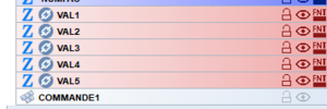
If the values present in the input file are not grouped (that is to say they are in different places in the text spool or in different XML tags), you will have to work with memory areas in order to recompose the character string necessary for the constitution of the ZPL instruction.
Once the memory areas are initialized with the values of the input file, we can modify the ZPL command in order to use them.
Pay attention to the order of the zones in the "list of objects": the memory zones must be located BEFORE the "Command" zone, so that they can be used by the latter!
Configuration of the ZPL command in order to use memory zones
As the dynamic content will come entirely from the memory zones, it is appropriate to configure the "command" zone so as not to look for a value in the file. Thus, if the input file is a text spool, the length of the area to be retrieved in the file must be 0. If it is an xml, the "XML field" parameter must be left empty.
The ZPL instructions, as well as the memory areas, will be placed in the "Pre-printed" and "Post-printed" parameters.
Pre-printed: ^RB64,2,3,14,20,25^RFW,E^FD[[VAL1]],[[VAL2]],[[VAL3]],[[VAL4]],[[VAL5]]Post-print: ^FS
Additional information
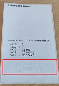
In order to carry out tests and check that writing is going well, it is possible to print the content of the RFID chip on the label using reading and printing instructions.
To do this, simply create another “command” area containing these instructions.
This “command” area must be configured as follows:
Pre-printed: ^RB64,2,3,14,20,25^FO50,50^A0N,40^FN0^FS^FN0^RFR,E^FS
In this example, the contents of the chip are read and printed on the label at coordinates x=50 points and y=50 points (^FO50,50) with an Arial font with a height of 40 points (^A0N,40 ).
Warning: the mask of the message structure (^RB: 64 bits divided into packets of 2, 3, 14, 20 and 25 bits) must be the same as that which allowed the writing, otherwise the content of the chip will be interpreted differently when reading and the printed result will not be as expected.


