ONYX - 9.0 - Usage
The main administration menus
Sommaire
- 1 Introduction (Foundation level)
- 2 Configuration management (Intermediate level)
- 3 Managing Robots (Foundation level)
- 4 Managing prints
Introduction (Foundation level)
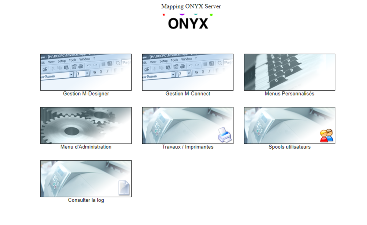
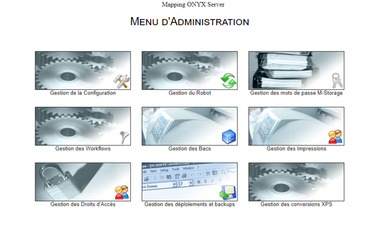
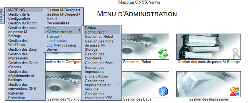
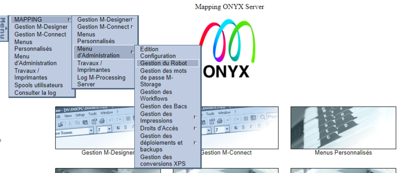
This menu which you can get to from the home page gives you access to:
• all the settings of the solution,
• entry points creation and configuration in Onyx Server (Scanfolder robots, listening servers, processing queues),
• execution and routing rules (Workflows) of the output and transfer points of the documents.
This documentation page will touch on the main menus, the other administration menus will be further discussed in another documentation page.
Configuration management (Intermediate level)
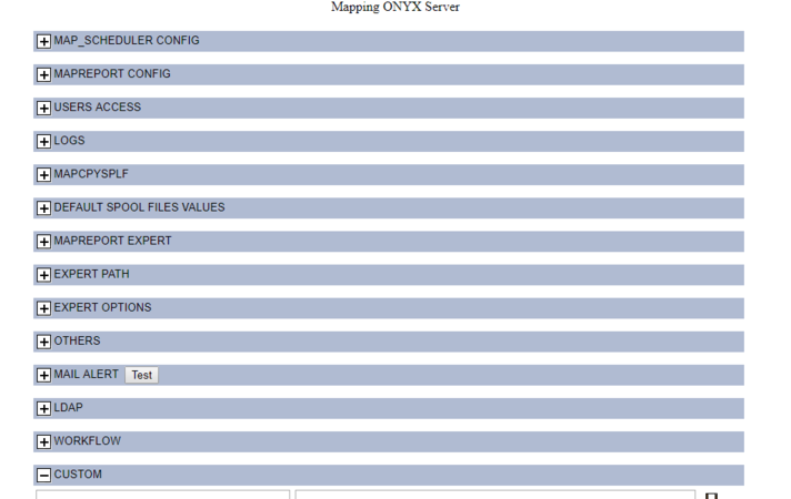
This interface gives you access to all the environment settings to manage the solution from its installation to its general configuration. Most values are given for information purposes and should only be edited with care, by either an advanced user or an admin of the solution. Information is organised in sections, each section identifying the contexts influencing the parameters.
These sections are displayed in condensed mode by default, to open a section and see the corresponding parameters, click on the "plus" icon. An input field allows you to edit the value of each parameter, click on the "save" button to save the changes made. Several changes can also be made at once, every parameter which was edited is then displayed in red until the changes are validated.
All the parameters in these sections are Onyx Server environment parameters which can be used as is in the execution engine (Workflows), as well as in the user scripts launched from the engine.
Example: use the PATH_TEMP parameter to build a temporary file path.
The Custom section which you can access from the bottom of the screen, allows you to create new parameters if needed which you will in turn be able to use in the engine.
To create a new parameter:
- Give a name to the parameter: with alphanumerical characters without spaces, case sensitive (square brackets are not required, they are only added for display purposes),
- Specify a value,
- Save.
Most sections will be seen in detail in this documentation, in their corresponding application contexts.
Managing Robots (Foundation level)
This interface manages all the robots configured in the solution, whether they are Scanfolder robots or listening servers.
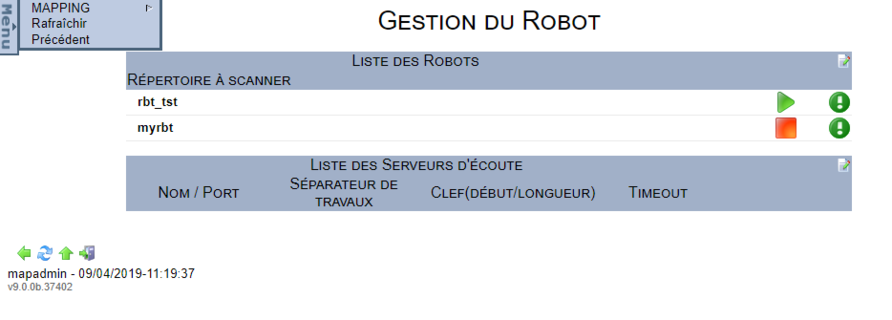
Upon first installation, the list is blank but it gives access to the ONYX server entry points creation/edition menus:
From the perspective of ONYX Server, a robot is an entry point in the solution, in other words it is a way for a third-party application to send an execution query. Robots are programs executed as background tasks (Service mode under Windows) to monitor data input, in a folder in the case of Scanfolder robots, or on a network port in the case of listening Servers. Each input file is successively put through the Workflow execution engine to be processed appropriately.
Scanfolder Robots (Foundation level)
Introduction
- Scanfolder robots monitor folders in the file system, to control input files (sent as copies or transferred FTP/SFTP). Files detected in the folder are successively sent (one by one) to the execution engine to be processed according to the rules defined in the Workflows.
- A robot which is configured in ONYX Server can only monitor one folder, in the same way, a folder of the file system can only be monitored by one Scanfolder robot. You must therefore create and configure as much Scanfolder robots as there are folders to monitor. Each robot is independent from the others, which means that several files can be processed at the same time, but by different robots.
Creating/Editing/Deleting
Clicking the ![]() icon, let's you create or edit robots which were already configured (if they are not being executed).
icon, let's you create or edit robots which were already configured (if they are not being executed).
To configure a robot the following parameters must be specified:
Name = gives a name to the robot.
- This parameter is optional but highly recommended. The name of a robot constitutes an environment variable which is accessible and can thus be used in the Workflows.
- ONYX Server ensures that the names used for the different robots are unique.
Folder to scan = path of the folder monitored by the robot.
- This parameter is required.
- It can point to a network drive or a UNC path (under Windows). Be careful of access rights.
- ONYX Server ensures that the folders scanned by the different robots are unique.
- ONYX Server can create the specified folder if it does not exist.
CMD = action executed on every file detected after it was properly processed by the execution engine.
- This parameter is required.
- Delete: the files detected and processed are deleted from the monitored folder.
- Move: the files detected and processed are moved to another folder, to be archived for example.
Destination folder = destination path of the files processed.
- This parameter is required if the movement command was chosen previously.
- ONYX Server ensures that the destination folder is different from the monitored folder.
- ONYX Server can create the specified folder if it does not exist.
Delay = waiting time interval between two folder monitorings. Given in seconds.
- This parameter is required.
On Error = defines the behaviour of the robot when a processing error is reported on a detected file.
- This parameter is required.
- Stop: the robot stops and the error file stays in the monitored folder.
- Continue: the robot continues to process the next files while the error file stays in the monitored folder and is renamed with the added suffix _FAILED (keyword configured by Mapping to prevent the robot from processing this file again next time the folder is monitored).
- Retry: the robot continues to process the next files while the error file stays in the monitored folder. Next time the folder is monitored, the robot will try to process this file again.
Workflow = name of the Workflow to execute.
- This parameter is optional. If nothing is specified the root Workflow is executed by default.
Filter = excludes files from the robot monitoring.
- This parameter is optional.
- Example: *.tmp → the .tmp files in the monitored folder are not processed by the robot.
Accept = restrain the type of files to process.
- This parameter is optional.
- Example: *.xml → .xml files in the monitored folder are the only ones processed by the robot
Notes:
To create a new robot, specify all the needed parameters, click on the "Save" button to add the robot to the server configuration.
To edit an existing robot, edit it or its parameters, then click on the "Save" button to edit the robot in the server configuration.
To edit or delete a robot, the latter must absolutely be stopped.
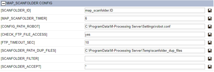
Environment parameters:section MAP_SCANFOLDER CONFIG
This part displays the details of the environment parameters of the Scanfolder robot section.
SCANFOLDER_ID = default naming suffix for temporary files linked to robots (see part Use here-after).
MAP_SCANFOLDER_TIMER = default waiting time interval (in seconds) suggested upon creating a new robot.
CONFIG_PATH_ROBOT = path of the configuration file of the robots.
Example under Linux: /apps/mapping/conf/robot.conf
FTP_TIMEOUT_SEC = maximum waiting time (in seconds) to access an input file in the monitored folder in FTP as the CHECK_FTP_FILE_ACCESS parameter is activated ("oui", "yes", "true" or "1" are accepted).
SCANFOLDER_PATH_DUP_FILES = moving path of the files after processing when the latter have been detected as having already been processed by Onyx Server, in other words path of the files with identical names.
SCANFOLDER_FILTER = exclusion filter for files to process. It can be applied to all the configured robots and can be overloaded by the local parameters of each robot. Several files can be specified, separated by a semi-colon " ; ".
SCANFOLDER_ACCEPT = restriction filter for files to process. It can be applied to all the configured robots and can be overloaded by the local parameters of each robot. Several files can be specified, separated by a semi-colon " ; ".
Use
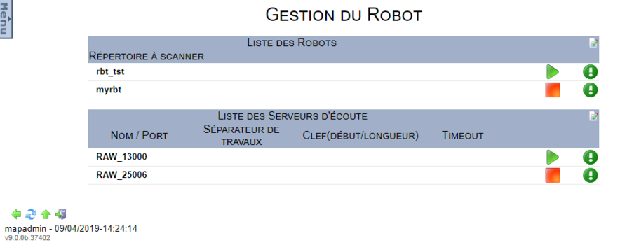
Once the robots created and configured, they are shown in the managing window.
This screen allows you to:
Once started, a robot is a process executed continuously as a background task. The associated ONYX Server binary is map_scanfolder. The list of active system processes (Task manager under Windows / command ps –ef under Linux) displays as much processes map_scanfolder[.exe] as there are robots started.
Note:
Under Windows, robots are installed as Services in the Windows Service Manager. They are registered as such when first starting the robot. The corresponding Service is named based on the name of the robot if it is specified (which is why names need to be unique) or based on the name of the monitored folder (which is why names need to be unique). Example: Mapping_ScanFolder_SCAN_TXT. Every Windows Service created by the robot is configured in manual start by default, however, this can be changed to an automatic system start afterwards.
- Temporary files associated to the robots:
Once started, each robot creates two files in the Onyx Server temporary folder. The first one is named based on the name of the monitored folder with special characters replaced by ‘_’ and the value of the SCANFOLDER_ID ("map_scanfolder.ID" by default) parameter as an added suffix.
Example: E__InputData_TXT_map_scanfolder.ID
The second file is named based on the system number of the associated map_scanfloder[.exe] process.
Example: 75668.pid.
These files are only intended for internal use of the process and are automatically deleted after the robot is stopped. Nonetheless, the Web interface relies on these files to indicate the status of the robots.
- Useful command lines:
To start a robot:
- Linux (after the environment was loaded) /apps/mapping/bin/map_scanfolder -name:SCAN_TXT
- Windows C:\Program Files(x86)\M_Processing Server\Applications\map_scanfolder.exe -name:SCAN_TXT
To stop a robot:
- Linux (after the environment was loaded) /apps/mapping/bin/map_scanfolder -name:SCAN_TXT –stop
- Windows C:\Program Files(x86)\M_Processing Server\Applications\map_scanfolder.exe -name:SCAN_TXT –stop
If the robot is not named, set each parameter that describes the robot as an argument of the previous commands (hence the prior advice on robots unique names)
Listening servers
Introduction
- A listening server type of robot monitors a listening port to control input data (data sent by a remote system by direct transfer in RAW protocol). The robot retrieves the data and rebuilds the files locally, it then sends them successively (one after the other) to the execution engine so that they can be processed according to the rules set in the Workflows.
- A robot which is configured in ONYX Server can only monitor one network port, in the same way, a network port can only be monitored by one listening server. You must therefore create and configure as much listening servers as there are ports to monitor. Each robot is independent from the others, which means that several files can be processed at the same time, but by different robots.
Creating/Editing/Deleting
Clicking the ![]() icon, let's you create or edit robots which were already configured (if they are not being executed).
icon, let's you create or edit robots which were already configured (if they are not being executed).
To configure a listening server the following parameters must be specified:
Name = gives a name to the robot.
- This parameter is optional but highly recommended. The name of a robot constitutes an environment variable which is accessible and can thus be used in the Workflows.
- ONYX Server ensures that the names used for the different robots are unique.
Port = number of the network port the robot listens to.
- This parameter is required.
- ONYX Server ensures that the ports the different robots listen to are unique.
Job separator = character or string of character which divides a wide network stream into several files.
- This parameter is optional.
Key (Length Start) = allows you to add information to the name of the temporary file built by the robot.
- These 3 parameters are optional.
- This information is looked for in the network stream, according to the keyword, while ignoring X characters after the keyword (start parameter) and retrieving N characters (length parameter).
- This information can notably be used in the Workflows as a condition.
Timeout = network waiting time (in seconds).
- This parameter is optional.
- It allows you not to block the network port in the event of a problem coming from the stream transmitter. The robot shuts down the connection after this period of inactivity as it considers that the established connection is no longer active.
Notes:
To create a new listening server, specify all the needed parameters, click on the "Save" button to add it to the server configuration.
To edit an existing server, edit it or the needed parameters, then click on the "Save" button to edit the server configuration.
To edit a server, the latter must absolutely be stopped.
To delete a robot, the latter must absolutely be stopped.
Environment parameters:section MAP_RAWD CONFIG
In the Mapping Operations Menu which manages configuration, a section is dedicated to listening servers. The details of the environment parameters are given below.
MAPRAWD_ID = default naming suffix for temporary files linked to servers (see part Use here-after).
MAPRAWD_CONFIGFILE = path of the configuration file of the listening servers.
Example under Unix: /apps/mapping/conf/maprawd.conf
MAPRAWD_SERVERSTDIN = path of the file towards which the standard input is redirected (stdin).
MAPRAWD_SERVERSTDOUT = path of the file towards which the standard output is redirected (stdout).
MAPRAWD_SERVERSTDERR = path of the file towards which the standard error output is redirected (stderr).
Use
Once the robots created and configured, they are shown in the managing window.
This screen allows you to:
- See the log of a listening server: ![]()
Once started, a listening server is a process executed continuously as a background task. The associated ONYX Server binary is map_rawd. The list of active system processes (Task manager under Windows / command ps –ef under Linux) displays as much processes map_rawd[.exe] as there are robots started.
Note:
Under Windows, listening servers are installed as Services in the Windows Service Manager. They are registered as such when first starting the robot. The corresponding Service is named based on the name of the network port (which is why names need to be unique) and the name of the job separator. Example: Mapping_Rawd_13000, Mapping_Rawd_25006_SEP.
Every Windows Service created by the robot is configured in manual start by default, however, this can be changed to an automatic system start afterwards.
- Temporary files associated to the listening servers:
Once started, each listening server creates a folder in the Onyx Server temporary folder. It is named based on the name of the network port and the job separator with a map_rawd.ID file which contains the number of the associated process.
Example: …\Temp\map_rawd_25006_SEP\map_rawd.ID
- Useful command lines:
To start a robot:
- Linux (after the environment was loaded) /apps/mapping/bin/map_rawd -start -name:RAW_25006
- Windows C:\Program Files(x86)\M_Processing Server\Applications\map_rawd.exe -start -name:RAW_25006
To stop a robot:
- Linux (after the environment was loaded) /apps/mapping/bin/map_rawd -stop -name:RAW_25006
- Windows c:\Program Files(x86)\M_Processing Server\Applications\map_rawd.exe -stop -name:RAW_25006
If the robot is not named, set each parameter that describes the robot (network port and job separator) as an argument of the previous commands (hence the prior advice on robots unique names).
Managing prints
Managing the spooler
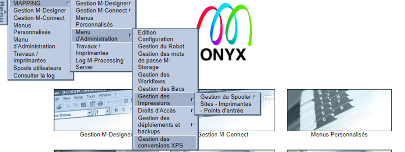
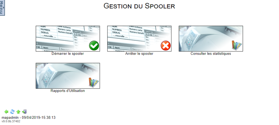
As mentioned earlier, the ONYX Server Spooler is the core of the solution. It manages streams, processings and printers. From the Administration Menu, then Managing prints and finally Managing the Spooler, the following interface allows you to:
- Start the Spooler = Start the Spooler.
- Stop the Spooler = stop the Spooler.
- See statistics = See output statistics.
- Usage reports = See the usage reports of the solution.
Once started, the Spooler is a process executed continuously as a background task. The associated ONYX Server binary is map_daemon[.exe].
Note:
Under Windows, the Spooler is installed as a Service in the Windows Service Manager. It is registered as such when first starting the Spooler. The corresponding Service is named Mapping_Spooler. It is is configured in manual start by default, however, this can be changed to an automatic system start afterwards.
- Temporary file associated with the Spooler:
Once started, the Spooler creates a map_daemon.ID file in its ONYX Server installation folder:
- by default under Windows C:\ProgramData\M-Processing Server\Spooler
- by default under Linux /apps/mapping/spool
- Useful command lines:
To start the Spooler:
- Linux (after the environment was loaded) /apps/mapping/bin/map_daemon start
- Windows C:\Program Files (x86) \M-Processing Server\Applications\map_daemon.exe" start
To stop the Spooler:
- Linux (after the environment was loaded) /apps/mapping/bin/map_daemon stop
- Windows C:\Program Files (x86)\M-Processing Server\Applications\map_daemon.exe" stop
Managing sites and queues
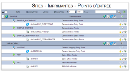
From the Administration Menu, then Managing Prints and finally Managing Sites / Printers / Input points, the interface shown displays the list of all the queues configured in the Spooler, organised per sites.
For example, a SAMPLE site was declared, in which three queues (an input and an output one) are configured. Three other queues are declared outside the site and displayed in a default site called Principal.
From this interface, inside every site, you are able to:
Create a site: Sites are a logical way to organise queues.
Create an output queue: It will be linked to a physical printer.
Create a customised processing queue: It runs a client script (shell).
Create a Mapping processing queue: It executes a Workflow.
Important notes:
- All the objets created and configured must have a unique name no matter their type (an output printer cannot have the same name as a site).
- Once created and configured, the name of an object cannot be changed anymore. If necessary, the object must be deleted and recreated.
Definitions
Site:
A site can be defined as a Mapping object, its aim is to organise the different queues. The sites can represent different countries, regions, agencies or stores.
Queue:
A queue can be defined as a Mapping object which receives the list of files to process and organises processings according to priorities. The queue does not establish any other connection with a physical printer. It is an object which only manages a list of files. It is at least linked to a device which does establish connections with physical hardware. If it is in Ready or Suspended status, then the files will not be processed by the device.
Device:
A device is defined as a Mapping object which communicates with the printer depending on specific parameters such as the IP address, protocol, … It must be linked to one queue only. It can be in Ready, Suspended or Error status. In both the last cases, the files will not be processed by the device. Several devices can be connected to one queue (load balancing).
Creating a site
Sites allow you to classify queues in the Spooler to organise the prints managing display into a hierarchy. A site can also be used as a display filter or search filter in the operating view.
To create a site, click on the ![]() button.
button.
Note:
Sites can be created inside other sites, which means you can build a complex display tree system. To do so, use the creation button on the line of the site which is concerned.
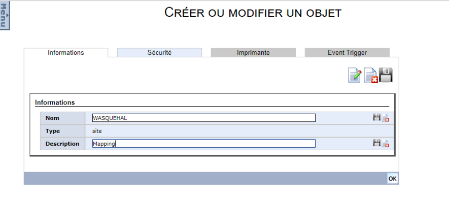
In the input screen, specify each of the following information, validate it by clicking on "save":
- Name = Name of the site (required, it must absolutely be unique).
- Description = optional.
Once the site is configured, click on "OK" to save it (3).
Creating an input point
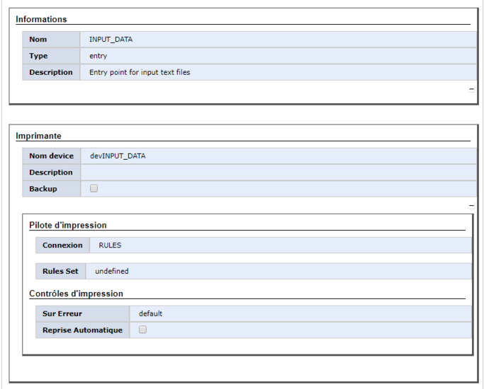
An ONYX Server input point is a queue which runs Mapping processings that are also called Workflows. It is made up of two objects:
- A queue to receive queries (jobs).
- A device, or engine, to handle queries and perform processings.
To add an input point in a site, click on the button on the line of the site which is concerned.
After having specified the needed information, validate it by clicking on "Save".
- Queue
- Name = name of the queue (required).
- Description = description of the queue.
After validating the name, the creation form of the associated device is displayed.
- Printer
- Device Name = name of the associated device (required).
- Description = description of the device.
- Printer driver
- Connection = The default type of driver is RULES and cannot be changed (calls the execution engine).
- Rules set = Choose the executed Workflow in the drop down menu. The root Workflow is executed by default (‘Default’ or ‘Undefined’).
- Print controls
- Upon error = Device behaviour in case of error:
o Default or Stop: in case of error, the current processing stops, the device also stops in error status.
o Continue: the current processing stops in error status while the device continues to process the next queries.
o Ignore: the current processing is considered as done, the device continues to process the next queries. This value is not recommended, except for special cases.
- Error recovery = Error recovery: if activated, an error inducing processing is relaunched.
- Maximum time = maximum time during which a processing in error status is relaunched before really being considered as being in error status. The device behaviour upon error is then taken into account.
Creating a printer
An ONYX Server printer is a queue which communicates with physical printing hardware. It is made up of two objects:
- A queue to receive printing queries (jobs)
- A device or printer, to handle the queries and send data to the physical hardware.
To add a printer in a site, click on the ![]() button on the line of the site which is concerned.
button on the line of the site which is concerned.
Fill in the needed information and validate it by clicking on the "save" button.
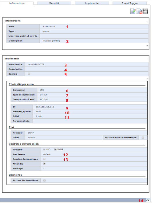
- Queue
- Name (1) = name of the queue (required).
- Description (2) = description of the queue.
After validating the name, the creation form of the associated device is displayed.
- Printer
- Device Name (3) = name of the associated device (required).
- Description (4) = description of the device.
- Backup (5) = if this is activated, it allows you to set a backup printer which will automatically take over the main printer in the event of an error.
- Printer driver
- Connection (6) = type of connection. ONYX Server implements several types of communication protocols, the LPR protocol being the most widespread and used here.
- Type of print (7) = type of print. The default type means that the associated hardware is a physical printer. The MAPPING type indicates communication with another ONYX Server Spooler (remote), and allows you to activate the compression of the exchanged streams.
- XPS Compatibility (8) = XPS compatibility. This allows you to communicate directly with the associated physical printer, in its direct printing language. XPS streams are converted on the fly according to the selected profile, then sent to the printer, without depending on any driver.
- IP (9) = IP address of the physical printer.
- Remote queue (10) = internal name of the physical printer: generally PASS if it is directly connected to the network, or the name of the port on the box (HP JetDirect for instance) if it was used to connect the printer to the network.
- Time (11) = maximum waiting time of a network communication.
- Status
Allows you to question the physical printer to see its status displayed in the operating view.
- Print controls
Allows you to question the physical printer to check the status of the print job. This additional communication is described in detail in the User Guide. The default settings can be used at first.
- Upon error (12) = device behaviour upon error:
o default or stop = the current processing and the device stop in error status.
o continue = the current processing stops in error status while the device continues processing the next queries.
o ignore = the current processing is considered as done, the device continues to process the next queries. This value is not recommended, except for special cases.
- Error Recovery (13) = Error recovery: if activated, an error inducing processing is relaunched.
o Maximum Time = maximum time during which a print job in error status is relaunched before really being considered as being in error status. The device behaviour upon error is then taken into account.
o Recovery mode: in its entirety or per page.
Once the (basic) configuration of the printer done, save the new object (14).
Printer advanced configuration
Printer driver
The printer driver is configured with all the parameters regarding, solely, the connection to the physical printer for data delivery. The configuration of the printer driver depends on print controls: error report, printer status...
Connection
- LPR (default value, recommended)
Line Printer Remote is the standard connection used for network printers. The Spooler connects to the lpr port of the printer (515) and sends the data. This protocol implements connection and communication controls throughout the delivery process. It is supported by almost all printers and can also communicate with printing servers.
- RAW
This is another network protocol, in other words a connection to a port (which has to be specified) followed by data delivery and a log out. This protocol does not implement any control.
- SHELL
Used for queues with the same name, the SHELL type device is not directly connected to a physical printer, it is to a program such as a bat or a shell script depending on the operating system.
- RULES
Used for input queues, the RULES type device is not directly connected to a physical printer, it is to the ONYX Server Workflow execution engine.
- USB
The printer must be connected to a USB port. The name of the port must also be specified.
- SERIAL
The printer must be connected to a serial port. The name of the port must also be specified.
- LOCAL OS SPOOLER (only under Windows)
The device sends the file to a pinter which was declared on the Windows printing server. The name of the Windows printer must then be selected in the Remote_queue drop down menu.
- DUMMY
Test connection. Files are processed but are not really sent.
- IPDS
The printing protocol used is IPDS. This protocol allows you to print AFPDS streams with two-way communication between the server and the printers.
The Email type device is not connected to a physical printer, it is responsible for sending documents received by e-mail.
Print type
- DEFAULT
Default protocol.
- MAPPING
Used to send data to a remote Mapping Spooler, this protocole notably allows you to compress files before they are sent to the remote server.
- AXHIOM (only available for RAW and USB protocols).
This protocol is specific to AXHIOM printers.
- ESCPOS (only available for RAW and SERIAL protocols).
This protocol is specific to EPSON receipt printers.
- SAMSUNG (only available for the RAW protocol).
This protocol is specific to SAMSUNG receipt printers.
- ZEBRA (only available for the RAW protocol).
This protocol is specific to ZEBRA receipt printers (using the LPR protocol by default is recommended for ZEBRA thermal printers).
Fonts resolution
This parameter sets files resolution to create and send AFPDS fonts. The value is given in dpi (240 or 300). This parameter concerns IPDS connections.
Activate log
This parameter activates IPDS traces. The latter are created in the \afpds\ipds sub-folder of the original ONYX Server folder.
This parameter concerns IPDS connections.
XPS compatibility
This is the conversion profile to use when sending XPS files. The displayed profile is included in the <label> parameter of the XPSConfig.conf file. If the file to print is in XPS format, then the selected conversion profile is used (to convert PCL, ZPL…). If the file is not in XPS format, then the parameter is ignored and no conversion is done. If there is not any specified conversion profile, the file is sent unconverted (Caution: The result of sending an XPS file to a printer which does not support it is usually unreadable characters printed continuously until the printer bins are completely empty…) This parameter concerns LPR, RAW, IPDS and EMAIL connections (e.g. to convert to PDF and add attachments).
IP address
This is the destination address of the printer (or print server). The IP address of the peripheral or its DNS name can be used. This parameter concerns LPR, RAW and IPDS connections. In the case of an EMAIL printer, the IP address of the SMTP server is used.
Remote Queue
This is the name of the internal queue of the printer (or print server). The name of the queue depends on the printer manufacturer, the most common name being PASS, it can also be RAW, PR1, PR0, PR3, TEXT, mp or else. Caution: this parameter is usually case sensitive. In the case of a print server, it is the destination queue on this server, in other words in the case of a Mapping server = name of the queue; for a Windows print server = name of the printer ; for iSeries = name of the OUTQ… For a LOCAL OS SPOOLER connection, the selection list is composed of the names of the printers which are declared in the Windows spooler. This parameter concerns LPR and LOCAL OS SPOOLER connections.
Port
This is the connection port to the printer (or print server). In LPR connection, the default port is 515 (this cannot be changed). In RAW connection, the most common value is 9100. In IPDS connection, the most common values are 9100 or 2501. This parameter concerns LPR (this cannot be changed), RAW, USB, SERIAL and IPDS connections.
Time
This parameter is a network communication timeout which is taken into account in every step of the communication process with the physical printer: connection, network packet delivery, acknowledgement receipt. The * value means that the network timeout is not controlled so that the printer does not report an error. This parameter concerns LPR, USB, SERIAL, LOCAL OS SPOOLER connections.
Shell
This is the complete path of the script executed by the device (a .bat on Windows, a .sh on Unix or Linux). This parameter concerns SHELL connections.
Rules Set
This is the name of the Workflow executed by the device. This parameter concerns RULES connections.
Customised
This parameter allows you to add customised parameters (metadata) when sending via LPR. The parameters available are those of the map_lpr command (beware not to use an already existing parameter: see the log of the queue for more details on the map_lpr command executed).
Example: -sleep:10 = to add a 10 seconds break in between each file.
Status
This parameter allows you to activate or not to activate the control of the printer status, with display in the Spooler interface. Retrieval of the printer status does not depend on the print control which is done in addition to the data delivery to control errors. Using the status control implies that the destination printer (or peripheral) is able to send this type of information.
Caution: if the printer is connected to the network with an additional appliance (such as AXIS or HP JetDirect), the information is retrieved via the appliance, not the printer. The status retrieve is then that of the appliance, not that of the printer.
With status control activated, the web interface of the Spooler can display the status of the printer (ready, off-line, paper jam…).
If automatic upgrade is requested, M-Processing Server retrieves the status of the printer only at the time a file is sent. The displayed information then corresponds to the status of the printer during the last Mapping print job.
Protocol
- NONE
No printer status query is sent.
- SNMP (recommended mode)
This SNMP protocol is used to control statuses. It is the most reliable and comprehensive protocol. It is supported by most recent printers and allows you to display the content of the printer control panel. To control the SNMP capacities of the peripheral manually, use the mapsnmp[.exe] command.
- LPQ
The LPQ protocol allows you to set a basic information retrieval of the pinter status. Only the status (active or inactive) is displayed.
- PJL (this mode is not recommended, it is kept only for backward compatibility purposes)
The status of the printer is retrieved using the PJL protocol. This protocol is quite thorough but is not very reliable because it lacks standardisation (the PJL implementation is different according to the manufacturer, or even the printer itself). Error messages are not standardised (hence the parameters to call a PJL message file and a language)
Time
This corresponds to the time given to retrieve the printer status. When the automatic upgrade is activated, be careful not to put too small time intervals so that the system is not saturated.
Automatic upgrade
This refreshes the printer status automatically even when no print job is done. It can be useful to an operator which manages an entire stock of computing equipment and wants to control the overall status of the printers.
Print control
Print control is used:
- to check if a file was completely printed
- for automatic recoveries if necessary
Protocol
- SNMP (recommended mode)
This SNMP protocol is used to control statuses. It is the most reliable and comprehensive protocol. It is supported by most recent printers. SNMP manages the page count which allows you to check if all the pages of a file were printed.
- LPQ
The LPQ protocol allows you to set a basic information retrieval of the pinter status. It does not manage page count which means that automatic recovery can only be used for the whole document.
Upon error
This defines the device behaviour in case of processing or printing error.
- Default
Default behaviour according to the DAEMON_NO_HOLD_ON_ERROR and DAEMON_DONT_HOLD_ENTRY_ON_ERROR configuration settings. The default behaviour of devices for the value NO, is the Stop status.
- Stop
In case of error, the current spooled file is in error status. The Mapping device is also in error status. In this case, any print job assigned to this printer is stopped until the Mapping device is restarted (via the Web interface or with a command). If a backup printer is defined, the following files are printed by the backup printer.
- Ignore (this is not recommended)
Errors are ignored and the current spooled file is considered as processed. The next spooled file is sent to the printer.
- Continue
the device stays in ready status and the current spooled file is in error status. The next spooled file is sent to the printer.
Automatic recovery
If the box is ticked, the spooler sends the file back to the printer in case of error. In this case, a maximum recovery time and recovery mode (complete or partial) need to be set. During the recovery time, the device is in error status but the spooled file is being printed. If the automatic recovery fails, then the spooled file is also in error status. If it succeeds, the device is then in ready status.
- Time
This is the maximum time during which the spooler relaunches the print job.
Caution: some printers can print the file several times.
- Mode
This allows you to define the type of file recovery:
- Complete: the entire file is sent back, starting from page 1
- Page min: the file is sent back starting from the last printed page minus n pages (n being defined as the length of the paper path)
- Page max: the file is sent back starting from the last printed page plus n pages (n being defined as the length of the paper path)
The number of pages retrieved from the printer is not always completely reliable. Some printers count the pages starting from the moment the pages are at the buffer, and not physically printed. If the print job is interrupted during processing and the printer counter indicates 50 pages, it is possible that only 47 pages were physically printed (the other 3 being somewhere between the input and output bin = still following the paper path).
On other printers (this is a rare case), the counter is late compared to the number of pages which were actually printed, it is then necessary to count a few pages.
Examples:
If the last page sent back to the printer is page 50 and the automatic recovery is set to Page min with a paper path length of 3 pages, the paper job is relaunched at page 47. If the last page sent back to the printer is page 50 and the automatic recovery is set to Page max with a paper path length of 3 pages, the paper job is relaunched at page 53.
Wait
The wait parameter configures the spooler to wait for the final print receipt of the current spooled file before sending the next one. This is the default mode. If the parameter is not activated, pages are not being counted anymore.
Page unit (PerPage)
The page unit depends on the type of printer and counter. It is used to check that all the pages of a spooled file were printed. If the printer prints documents sheet per sheet (cutsheet), which corresponds to most laser workgroup printers, then the printer counts per physical page. This does not raise any compatibility issues because Mapping also counts per page. the page unit is 1 (by default). However, in continuous paper printers which use paper rolls (continuous paper laser, impact or thermal printers), the counter is defined in printed distance (usually in inches). The size of the paper must then be calibrated by specifying the page unit. For instance, on a thermal printer which prints 4 inches long labels, a page unit of 4 must be defined.
Activate the banners
Banners are pages which act as separators and are added before and after the print file. Refer to the specific part of this Guide on creating and using print banners for more information.
Advanced configuration of queues
Any Mapping queue, whatever type they are, features two advanced configuration tabs: a Safety tab to manage access rights to the queue and an event manager to initiate specific actions.
Note:
The printer tab displays all the devices configured and linked to the queue in the same way the Information tab does.
Safety
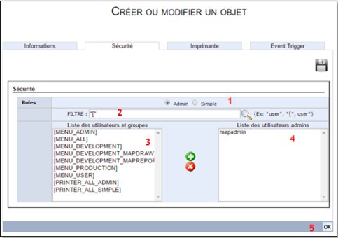
This tab allows you to manage access rights to the queue. This goes along with creating users and user groups as well as the management of access rights to the Web interface menus. To assign access rights to a queue:
(1) Select the type of access:
- Admin: admin users have all action rights on the queue and its devices, as well as on all the jobs in the queue (even those that they do not own).
- Simple: simple users only have action rights on the jobs they own. Simple users do not see the jobs of other users, even if they are put in the same queue.
(2) Use filters to search for a group or a specific user
Note:
A filter is applied to the ‘[‘ character by default so that only user groups are displayed (it is usually recommended that you manage access rights using user groups).
(3) The list on the left displays all the available users and groups which were not assigned rights on the queue yet. Select one or several elements (to select multiple elements at once hold the Ctrl key down), then, click on ![]() to assign the users or groups to the list on the right.
to assign the users or groups to the list on the right.
(4) The list on the right displays all the users and groups which were already assigned rights (Admin or Simple) on the queue. Select one or several elements (to select multiple elements at once hold the Ctrl key down), then, click on ![]() to withdraw rights from the users or groups.
to withdraw rights from the users or groups.
(5) Validate this action once the configuration is finished.
Event Trigger
This tab allows you to monitor four levels of events on the queue to trigger specific actions.
Type of events
The four types of events are:
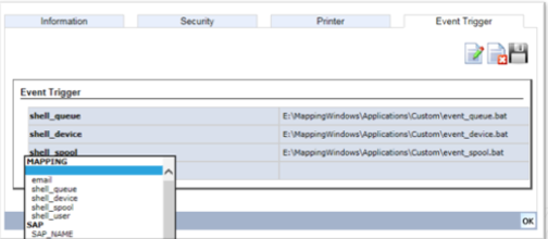
- Shell_queue: a queue changes status (from Suspended to Ready and vice versa).
- Shell_device: a device changes status (from Suspended to Ready and vice versa)
- Shell_spool: a job in the queue changes status (new job, switch to Ready, Error, Kept, etc.)
- Shell_user : an event is automatically triggered by a user action (click on a button).
The three first events are automatically triggered by the ONYX Server Spooler so that the user can monitor them using action scripts. When an event is triggered, the Spooler runs the configured script.
Below is an example of configuration with the three monitored events, each one using a specific script:
Note:
The email parameter in the drop down menu of events is used to define an email address which can be used in the script(s). The settings of the SAP section are used in case of a connection with the ERP SAP.
Environment variables
As mentioned previously, the ONYX Server Spooler launches the execution of configured scripts. this implies that all the Mapping environment variables in the scripts are accessible and usable, particularly: PATH_BIN for the binaries path, PATH_TEMP for the temporary folder, PMAP_JOBNUM for the job ID, etc…
Depending on the type of event triggered, additional parameters are also accessible:
- Shell_queue: all the attributes of the queue
| MAP_QUEUE_NAME | Name of the queue E.g. INPUT_DATA |
| MAP_QUEUE_SITE | Name of the site in which the queue is declared
E.g. WASQUEHAL |
| MAP_QUEUE_STATUS | Status of the queue after the event was triggered
Values: hold | ready |
| TMAP_QUEUE_LISTEN | Listening modes of the queue
E.g. lpd |
| MAP_QUEUE_PATH_FILE | Job storage path
E.g. E:\MappingWindows\Spooler\global |
| MAP_QUEUE_PATH_QUEUE | Outdated parameter, not used anymore |
| MAP_QUEUE_BACKUP | Name of the backup printer(s), separated by a comma |
| MAP_QUEUE_DESCRIPTION | Description of the queue in the Spooler
E.g. Entry point for input text files |
| MAP_QUEUE_DEVICES | List of the printers linked to the queue (separated by a comma)
E.g. devINPUT_DATA |
| MAP_QUEUE_USERDATA_… | User data defined for the queue
E.g. values of shell_queue, shell_spool, … |
| MAP_RESULT | ready |
| MAP_USER_REQUEST | User which triggered the action Values: internal_user in this case |
- Shell_device: attributes of the queue (above) added to all the attributes of the printer concerned:
| MAP_DEVICE_NAME | Name of the printer
E.g. devINPUT_DATA |
| MAP_DEVICE_STATUS | Status of the printer after the event was triggered
Values: hold | ready | error |
| MAP_DEVICE_CONNECT | Outdated parameter, not used anymore |
| MAP_DEVICE_MODE | Type of connection
E.g. LPR, RULES, IPDS, … |
| MAP_DEVICE_SUBMODE | Type of print job
E.g. default, mapping, axhiom, … |
| TMAP_DEVICE_IP | IP address of the physical printer |
| MAP_DEVICE_SHELL | Script or program run
E.g. $PATH_BIN/map_809 (Workflows engine) |
| MAP_DEVICE_LOGIPDS | Activation of the IPDS logs |
| MAP_DEVICE_PORTIPDS | Activation of the IPDS logs |
| MAP_DEVICE_FONTRESOLUTION | Font resolution (IPDS) |
| MAP_DEVICE_PORT | Print port
E.g. 515, 9100, … |
| MAP_DEVICE_REMOTEQ | Internal name of the physical printer
E.g. PASS |
| MAP_DEVICE_XPSMODE | Name of the XPS on the fly conversion profile |
| MAP_DEVICE_TYPESTATUS | Status recovery protocol
E.g. NONE, SNMP, PJL, … |
| MAP_DEVICE_IMPTYPE | Type of PJL codes for status messages
E.g. PJL_REF |
| MAP_DEVICE_LANG | Language of the status messages (PJL protocol) |
| MAP_DEVICE_PATH_QUEUE | Outdated parameter, not used anymore |
| MAP_DEVICE_QUEUE | Name of the queue the printer is linked to
E.g. INPUT_DATA |
| MAP_DEVICE_TIMEOUT | Network connection timeout (in seconds)
E.g. 600 (for 10 minutes) |
| MAP_DEVICE_TIMEOUT_STATUS | Time given to retreive the printer status (in secondes)
E.g. 10 |
| MAP_DEVICE_REALSTATUS | Real status of the physical printer
E.g. Ready - running-idle |
| MAP_DEVICE_MSGW | Error message
E.g. Failed printing |
| MAP_DEVICE_BACKUP | Is the device a backup device? |
| MAP_DEVICE_MONITOR | Print control protocol
E.g. SNMP, LPQ |
| MAP_DEVICE_CUSTOM | Customised parameters |
| MAP_DEVICE_PERPAGE | Page unit |
| MAP_DEVICE_RULES | Name of the executed Workflow
E.g. Invoices.rules.xml |
| MAP_DEVICE_ONERROR | Behaviour of the device upon error
E.g. continue |
| MAP_RESULT | Result of the action which triggered the event
Values: hold | ready | error |
| TMAP_USER_REQUEST | User which triggered the action
E.g. internal_user in this case
|
Sending a file in a queue
The ONYX Server Spooler is seen as a "virtual" printer from a third-party application. To send files in one of the queues of the Spooler, the print commands are thus used. ONYX Server has its own print commands: map_lp locally, map_lpr remotely.
MAP_LP locally:
This is a direct query sent to the ONYX Server Spooler (the map_daemon program answers). Two parameters are required for this command:
- queue:XXX = name of the queue in which the file is sent.
- data:XXX = complete path of the file to send.
Other parameters are available with this command (argument --help to list them) amongst which the most common are:
- title:XXX = gives a title to the document in the queue displayed in the operating view.
- user:XXX = defines the user name of the owner of the document in the queue.
- map_hold = the file is send in hold status (it will be processed after).
- map_save = saves the file after it was processed.
- map_retention:NN = adds a retention time (in days) in the attributes of the spooled file.
Example: the following commands add a spooled file in hold in the INPUT_DATA queue which is owned by the mapadmin user. The spooled file has 15 days of retention time defined in its attributes and it will switch to save status once processed.
Under Windows:
"C:\M-Processing Server\Applications\map_lp" "-queue:INPUT_DATA" "-map_hold" "-map_save" "-map_retention:15"
"-user:mapadmin" "-data:D:\Data\extract\FR_DEMO.txt"
Under Linux:
"/apps/mapping/bin/map_lp" "-queue:INPUT_DATA" "-map_hold" "-map_save" "-map_retention:15"
"-user:mapadmin" "-data:/opt/data/extract/FR_DEMO.txt"
MAP_LPR remotely:
This is a standard network print communication. The data sent to the ONYX Server under the LPR protocol is received locally by the map_lpd program, the latter then instructs the Spooler to add the document in the queue.
Three parameters are required with this command:
- server :NNN.NNN.NNN.NNN = IP address (or DNS name) of the ONYX server.
- queue:XXX = name of the queue in which the file is sent.
- data:XXX = complete path of the file to send.
Moreover, depending on the configuration, the LPD listening server of ONYX Server does not necessarily use the port 515 (standard print port which may already be used by another application). In this case, the Mapping network port must be specified by the argument: -port:NNN .
Other parameters are available for this command (argument --help to list them), the most common ones being the same as for the map_lp command.
Example: the following commands add a spooled file in hold in the INPUT_DATA queue which is owned by the mapadmin user. this spooled file has 15 days of retention time defined in its attributes and it will switch to save status once processed.
Under Windows:
"C:\App\Mapping_client\map_lpr" "-server:192.168.217.57" "-queue:INPUT_DATA" "-map_hold" "-map_save" "-map_retention:15"
"-user:mapadmin" "-data:D:\Data\extract\FR_DEMO.txt"
Under Linux:
"/apps/mapping_client/map_lpr" "-server:192.168.217.57" "-queue:INPUT_DATA" "-map_hold" "-map_save" "-map_retention:15"
"-user:mapadmin" "-data:/opt/data/extract/FR_DEMO.txt"
