ONYX - 9.0 - Usage
ONYX Designer Dynamic Part
Sommaire
Dynamic Part (Map Tab)
Definition
The Map part of a project corresponds to the dynamic part of designs that are made according to the datastreams processed by the template. The main elements which can be placed in this part are data files printable information.
To design this part, select the "Map F" tab (and "Map B" for the duplex of the document). In this view, elements of the "Draw" part are displayed as watermarks so that positioning the data to be printed is easier.
"Spooled File"
To retrieve and identify data to be printed, designing a Designer project is done using an example file. This example file is an image of the production spooled file to format.
Designer supports two types of data files in native mode: paginated text files and XML files in Mapping format. Input file types are configured in the project properties.
Designer processes files with .PAG or .TXT extensions. Text files usually have a ".PAG" extension because they need to be paginated. Text files can be paginated by running the "MAPPAGIFS" command in Onyx Server where an argument specifying the number of lines per page ("Overflow") will be given.
XML files need to respect a particular syntax so that the application can properly process them. (see 6.3 XML Mode: syntax and specifications).
To open and display an example file in DESIGNER, the spooled file view needs to be activated in the Display Menu:

In the "Home" tab, click on ![]() and select the file you want to load in the application.
and select the file you want to load in the application.
The spooled file view then displays the data from the spooled file to format.

![]()
To help you design your project, you can preview the result without having to print the document. To do so, click on the Preview button in the Home menu.
XML: syntax and specifications
In XML mode, the design principles are the same and are put in application using an example file loaded in the application.
As stated in 4.2. Creating a project, to load a .xml document, it is important not to forget to go to the project Properties and check that in Parameters > Mode = XML.

The Spooled file view is then called the XML view and displays the content of the file in a tree view.

Data structure
XML files that are processed by Designer in native mode have to respect a specific pattern and syntax, such as:
<page name="..."> … </page> tags mark out the pages of the document. In the last example, there is only one page.
- <field name="...">value1</field> tags correspond to unit-based information (the equivalent of ‘zones’/'fields' in Designer).
- <group name="..."> … </group> tags refer to a particular number of lines which contain zones, such as a ‘group’ in Designer.
- <line name="…"> … <line> tags correspond to the lines inside of these groups.
If we were to use this structure with a paper invoice:
- <page name="..."> … </page> corresponds to the pages of the invoice.
- <group name="..."> … </group> marks out the body of the invoice (from the first line to the last).
- <line name="…"> … <line> describes every line in the body of the invoice.
- <field name="...">value1</field> can correspond to two things:
- If this tag is on the outside of a group, it corresponds to unit-based information in the invoice. In which case, value1 corresponds to the invoice number in the header, for instance, or to the client number, the type of invoice, etc.
- If this tag is inside a group, value1 corresponds to the value of the zone in the line. For instance, the product code, its name, price, etc.
XML pattern specifications
The specifications needed for Designer to process the file are the following:
The XML header needs to specify the file encoding.
Example : <?xml version="1.0" encoding="UTF-16" standalone="yes" ?>
The root tag of XML data needs to be called doc.
All tags mentioned hereafter need to have at least one attribute named name. Information will be identified, retrieved and formatted by the application via the use of this attribute.
The tags and attributes names are case-sensitive and need to be written in lowercase letters.
For the application to access it, data must be placed in pages in between the <page name="…"> and </page> tags. One document can contain several pages.
Inside a page, data is organised per unit-based fields (balise <field name="…">) or per information groups (balise <group name="…">).
Information groups are composed of lines (balise <line name="…">).
The lines contain unit-based informations (balise <field name="…">).
Here is an example of an XML file:

XML data can be placed on the outside of a page as information linked to the overall document and not to the page in particular. However this data will not be accessible to Designer and thus cannot be processed to design the document. Nonetheless, this data can be used in the M-Processing Server engine.
XML view in Designer

An XML example file is loaded in DESIGNER in the same way that is use to load a text file. In the XML view, data is displayed as a list of elements.
Page break on an XML field value
In the Proprieties of a group, generating a page break can now be triggered based on the change in value of the XML field.
For example:
<group name="groupe">
<line name="ligne">
<field name="id">1</field>
<field name="data"> data </field>
</line>
<line name="ligne">
<field name="id">1</field>
<field name="data"> data </field>
</line>
<line name="ligne">
<field name="id">2</field>
<field name="data"> data </field>
</line>
<line name="ligne">
<field name="id">2</field>
<field name="data"> data </field>
</line>
…
</group>
In this example, if the field used to generate a page break is the field "id" then the page break will be generated after the execution of the second line.
There are several options in the interface for the Page break parameter:
![]()


- None: the group does not generate any page break.
- Limit: the group triggers a page break based on a positioning limit.
- XML Field: the group triggers a page break based on the change in value of an XML field.
- Limit and XML Field: the group triggers a page break based on a positioning limit and on a change in value of an XML field.
When generating automatic page breaks, managing the recovery of headers is possible with the options "Header" and "Last header":

- Header: to choose the name of the line of the XML file which acts as header.
- Last header: if checked, only the last header is kept. The box is checked by default.
When generating a page break, the last header (or all of the above headings, if the option is unchecked) are used at the start of the new page.
In the XML file, if two header lines follow each other, they are considered as one single header.
If a page break is triggered just after a header line, that header line is not printed and is moved to the next page.
f
To display a list of items in an XML group as a table, the script tool must be used.
The rowtotable feature rearranges the lines of a group so as to obtain a horizontal distribution of the elements.
Syntax:rowtotable(name of the group, maximal number of columns in the table);
The rowtotable feature has two settings:
- Name of the group: contains the name of the group to be reorganized in a table, framed by double quotes.
- Maximal number of columns in the table: Maximal number of columns in the table.
Note: All the lines of a group should have the same name.
For example:
<group name="invoice">
<line name="item">
<field name="name">item 1</field>
</line>
<line name="item">
<field name="name">item 2</field>
</line>
<line name="item">
<field name="name">item 3</field>
</line>
<line name="item">
<field name="name">item 4</field>
</line>
<line name="item">
<field name="name">item 5</field>
</line>
<line name="item">
<field name="name">item 6</field>
</line>
<line name="item">
<field name="name">item 7</field>
</line>
<line name="item">
<field name="name">item 8</field>
</line>
</group>
To rearrange this group in a three-column table, use the following script:
rowtotable("invoice",3);
This script will effectively change the group which then becomes:
<group name="invoice">
<line name="item">
<field name="name_1">item 1</field>
<field name="name_2">item 2</field>
<field name="name_3">item 3</field>
</line>
<line name="item">
<field name="name_1">item 4</field>
<field name="name_2">item 5</field>
<field name="name_3">item 6</field>
</line>
<line name="item">
<field name="name_1">item 7</field>
<field name="name_2">item 8</field>
</line>
</group>
Dynamic elements
This part of the documentation presents the basic elements that can be added in the dynamic part of a project in order to get started with the main features of the application.
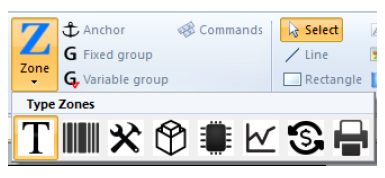
Zone
Definition
A zone is the main element, which allows you to retrieve information in the input data in order to position and format them in the final graphical document.
In text mode, the information is identified by the following three elements of data:
- a row number,
- a column number,
- a length.
In XML mode, it is identified by the name of the XML field (field tag).
A zone can only read one row at a time.
It is represented in the following two ways in the designing space:
- The zone is empty, no data is associated with it: an icon appears in its upper right corner.
![]()
- The zone is associated with an element of data, it appears without an icon.
![]()
A zone is identified by its name, defined in the properties window (see a.2 Creating a zone for more details).
Creating a zone
There are two methods you can use to create a zone:
Select the corresponding icon and its type in the Data tab and hold the button of your mouse down where you want the element to be placed. This method creates an empty zone. To link the zone to an element of data from the source file, select the data in the spooled file view (see the second method below) then, drag and drop it in the zone which was created previously, by holding down the Ctrl key.

Select the data to be recovered in the Spooled file view then, drag and drop it where you want, in the designing space to create a zone automatically linked to the data you selected.

Once the zone has been created, select it and display the 'Properties view to fill in the following information:

Name :
Name (of the zone): this information is used as internal information in Designer, it identifies the different objets in the project. When creating the zone from the data tab, this field is empty, its value is given by the data linked to it from the Spooled file view.
Text printed before/after: to add text before and/or after the retrieved information.
Position :
Position of the information in the data spooled file: column, length, beginning line.
This is also used to extract a certain quantity of information in XML mode.
Position in the document:
to change the position of the zone on the page.
Data Type:
defines how the Designer application processes the information retrieved (see a.3 Types of zones).
Font:
To set all formatting options: font, size, colour, framing, orientation, etc.
Types of zones
The Designer application offers various processing options according to the type of data to process:
- Text: prints plain text.
- Normal: copies the values located in the positions defined by the zone whether they are letters, numbers or blanks.
- Optimized: copies the characters located in these positions except for blanks at the beginning and end of these positions. The framing to the left or to the right is always observed. There is no shift due to blanks in the spooled file.
- Substitution: used to replace a value of the spooled file with another one stored in a file called replacevalue.txt. By default, this file is in its blank state in the Designer installation folder. To carry out the substitutions, place it in the lgobitmap folder. The folder needs to contain the values to be replaced followed by replacement values and separated by a tab. This sub-type is explained in further detail in 8.3. Replacing characters.
- Translate: substitutes a value for its translation in another language. A zone type Tools / Set Lang is used beforehand to define the file with the translated values. The program searches for the corresponding input in the translation file for each Text / Translate zone which is defined in the template. The file must be placed in the lgobitmap folder and its name must start with "Translate_".
- Compressed: zone displaying the recovered text into the dedicated space. The text occupies the width of the zone and adjusts the font size between a maximum and a minimum so that the text covers all the dedicated space.. If the minimum font size does not display the entire text, it is truncated and followed by "…".
- Truncated: zone displaying the recovered text into the space allowed by the zone width. If the text cannot be fully displayed, it is truncated followed by "...".
- Barcode: encodes and prints barcodes. The list of available barcodes can be seen in 8.1 Barcodes
- Tools: inserts a page number, images, … but also displays the total number of pages, pages in the current batch, …
- Page Number: numbers each edited page. The page number is not necessarily the same as that in the original spooled file. If M-Processing Server is set to exclude certain pages, the number of edited pages will not necessarily be the same as the number of pages in the original spooled file.
- Batch Number: displays the batch number.
- Page Number (Batch): displays the page number in the batch.
- Total Number of Pages: displays the number of pages in the document.
- Total Number of Batches: displays the number of batches in the document.
- Total Number of Pages (Batch): displays the number of pages in the current batch.
- Specific replacement: replaces a value in the spooled file processed by another value which was retrieved in a file. For example, the customer number displayed in the spooled file can be replaced with the customer's name which is retrieved in a database file.
- Image: prints out a different image depending on the value of the spooled file.
- Export: this type of zone allows you to retrieve information from the spooled file and export it to a physical file.
- Repl. File: retrieves text in a file. The name of the zone must correspond to the name of the file. The file must be in the lgobitmap folder and be called data_NAMEOFTHEZONE.txt (where NAMEOFTHEZONE is the real name of the zone). The row and length settings of the zone indicate the row and length of the text to be retrieved.
- Input Text: creates interactive input fields to design SOAP forms in PDF or HTML format. As the user opens the form generated in Adobe Reader or a web browser, he can fill in input fields and send data to an M-Processing Server URL in a Web entry point by clicking on the SUBMIT button, which is actually a Tools / Input Text zone called SUBMIT (system name).
- HyperLink: adds a URL link.
- Set Lang: to specify the file which contains the translations. The latter must be in the lgobitmap folder and its name must start with Translate_. This zone is not printed in the final document, it cannot be seen for preview nor mapping. The name of this zone is not really important, however it must be declared before any other Designer zone that requires translation. Then, the program searches for the corresponding input in the translation file for each Text / Translate zone defined in the template.
- XPS Message: Inserts an XPS file in the current page. This zone is a link to an XPS file which is on the M-Processing Server. This file must only contain one page and must also be placed in the lgobitmap folder (directly or in a sub-folder). It is not case sensitive. If changes are made to the XPS file, it will impact the projects that use it.
- XPS File: unlike XPS Messages, the files inserted with XPS File zones:
- can contain several pages.
- are whole pages.
- create additional pages in the output file.
- Metadata: indexes the document for archiving (non printed data). The length of the metadata is unlimited.
- Index: index zone by default, used in XPS manipulations and in M-Storage Manager as criterion.
- MapFrom: index reserved to send emails. The value of this zone will be used to specify the email sender.
- MapSend: index reserved to send emails. The value of this zone will be used to define the address of the recipient.
- MapCopy: index reserved to send emails. The value of this zone will be used to specify the copy recipient.
- MapBCopy: index reserved to send emails. The value of this zone will be used to define the recipient in hidden copy.
- MapNote: index reserved to send emails. The value of this zone will be used to define the body of the email.
- MapSubject: index reserved to send emails. The value of this zone will be used to define the mail subject.
- MapOrg: index reserved to send faxes. The value of this zone will be used to identify the sender.
- MapTo: index reserved to send faxes. The value of this zone will be used to define the recipient.
- MapUser: index reserved to send faxes. The value of this zone will be used to identify the owner.
- MapFormat: index reserved to send faxes. The value of this zone will be used to define the document format (.BMP, .JPG, .EXE, .PAG, .PDF, .TIF, .TIF_FAX, .TXT, .XLS).
- Memory: inserts and stores information (not printed) which will later be recovered and used in the template. (see 8.1.b. Combined data)
- Text: saves alphanumeric information and deletes the spaces after the text.
- Text with spaces: saves alphanumeric information and keeps the spaces after the text.
- Integer: saves integer-type digital information.
- Float: saves floating-type digital information.
- SQL: saves alphanumeric information found in a database using an SQL query.
- Protect SQL: saves alphanumeric information found in a database using a protected SQL query.
- Math. calculation: uses memory zones to perform a calculation.
- Memory Replacement: retrieves information saved in the memory zone.
- Memory Translate: saves alphanumeric information resulting from the automatic translation of the information retrieved in the spooled file.
- Graph: used to generate a graph using multiple elements of data
- Graph data.
- X-axis data.
- Y-axis data.
- Graph title.
- X-axis title.
- Y-axis title.
- Legend data.
- Minimum value of the Y-axis.
- Maximum value of the Y-axis.
- No. of intervals of the Y-axis.
- Rounding up/down to the nearest integer number on the Y-axis.
- Intercept of the Y-axis.
The construction of a graph is detailed in section 8.6. Drawing a graph.
Designer can automatically convert old graph types in complex graphics. This feature facilitates the conversion of old projects in XPS projects.
- Conversion: converts numerical data according to conversion rules (Euro to Dollar for example) defined in Onyx Server > Managing Designer Formats > Managing Rates (01=E1 ; 02=E2 ; …)
- XPS PrintTicket:
- Copy: number of copies to print.
- Input Bin: input bin number (printer paper feed).
- Output Bin: output bin number.
- Media Type: Type of paper (A4, A5, etc...).
- Force Front Side: determines the mode Simplex/Duplex when printing.
- Commands: adds data in the print stream, in printer language. As for the project properties, Document and Page (see 4.2. Creating a project), a "Commands" zone defines the printer language data for the following languages: PCL5, APFDS, PDF, ZPL, DPL, TEC, IGP, IPL and EPL. A zone can contain data for several different languages. When converting the XPS to the output language, the corresponding data to the output language will be used.
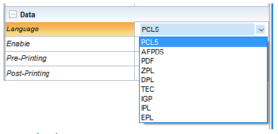
Language: select language.
Activate: enable zone for the selected language.
Pre- and Post-Printing: Data written before and after the retrieved data from the spooled file.

Writing hexadecimal data in the "pre-" and "post-printing" can be done using the following syntax: \x followed by the hexadecimal value of two characters.
Groups
Definition
A group can be used to retrieve several rows of a spooled file. It is defined by a beginning row and an end row. It is shown in red in the designing space:

A group can be fixed (fixed beginning and end rows) or variable (variable beginning and end rows).
Creating a fixed group
The creation of a fixed group, is similar to the creation of a zone.
- Create an empty group from the Ribbon menu, select the data of the source file, drag and drop it in the group you created beforehand while holding down the Ctrl key.

- Select data in the Spooled File view, use the drag and drop method to place it in the designing space to create a group automatically which is linked to the zone you selected in the spooled file.
Once the group is created, its informations must be specified in the Properties view:

Name:
- Name (of the group): this information is used as internal information in Designer, it identifies the different objets in the project. When creating the group from the data tab, this field is empty, its value is given by the data linked to it from the Spooled file view.
- Position in the document:
- Used to change the position of the group on the page.
- Position:
- Identifies the beginning and end rows in the block of information to recover.
- Offset: prints the position of the first row in relation to the group
- Option:
- Exclusive conditions: For one row of the group, a true condition will be executed exclusively without testing the following rows
- Table: allows zones of a group to behave like the cells of a table. Zones of the same line find themselves automatically linked. Resizing or moving a zone impacts the size and the position of the adjacent zones. In addition, the group's lines (or conditions) are visually represented in the designing window. The zones are vertically distributed according to their line. This option is detailed in 8.5.b. Drawing a dynamic table.
- Variable:
- Used to change the type of group: from fixed (the beginning and end rows are static) to variable (the beginning and end rows are variable and defined by conditions).
If the user requests a preview, no information will be printed. Indeed, a group only defines the limits between which the data is to be retrieved from the spooled file.
Given that the limits of the data selection zone are defined using the Beginning line and End Line fields of the group, the data must then be retrieved by creating one or more Zones inside the group.
In short:
- The selection zone of the data block is configured by creating a Group:
The data is retrieved inside this block of data by creating a Zone:

- All the rows of our block of data are retrieved using the preview function (Ctrl+w). Several Zones can be created from the data block, they can then be placed in the group and their formatting can be conditioned (see 6.4.c. Conditions).

Creating a variable group
A variable group uses the same principles as a fixed group i.e. it can be used to retrieve several rows of information in the spooled file. A variable group is used when the beginning or end row of the group is not always at the same place in the spooled file or if you do not want the information to always be printed at the same place on the page.
A variable group uses a start condition and an end condition. The group begins to run when a condition is validated and it stops when another condition is validated or when it has executed a certain number of rows. A variable group can be executed once or more times in the page.
The position of the values printed by a variable group can be variable.
For example, you can define the settings so that the values printed by a group are positioned after the values printed by another group. We refer to this as relative positioning.
You can also define the settings so that the invoice total is always printed one centimeter after the last product row (whether there are 5 or 20 rows). The position of the invoice total will therefore change according to the number of product rows in the invoice, for instance.
A group may vary in:
- size: the beginning and end rows are dynamically set by the conditions,
- print position: variable groups can be linked one after the other so that the following group is printed straight after the current group has been printed.
These two types of variable can exist separately or jointly.
To create a variable group, simply click the ![]() icon and draw the group in the designing space.
icon and draw the group in the designing space.
The Properties view is displayed so that the group information can be entered:

- Name:
- Name (of the group): this information is used as internal information in Designer, it identifies the different objets in the project. When creating the group from the data tab, this field is empty.
- Position in the document:
- Used to change the position of the group on the page.
- Position:
- Offset: prints the position of the first row in relation to the group.
- Option:
- Exclusive conditions: for a row of the group, a true condition will be performed exclusively without testing the following rows.
- Repeat: if the start condition appears several times, the group will run several times provided that the end condition has been validated in the meantime.
- MapOffice: used to check the design of a MapOffice group (see the Connect documentation on designing Office documents).
- Table: allows zones of a group to behave like the cells of a table. Zones of the same line find themselves automatically linked. Resizing or moving a zone impacts the size and the position of the adjacent zones. In addition, the group's lines (or conditions) are visually represented in the designing window. The zones are vertically distributed according to their line.
- Variable:
- Used to change the type of group: from fixed (the beginning and end rows are static) to variable (the beginning and end rows are variable and defined by conditions).
- Spacing: spacing before the printing of the group.
- Type of stop condition: used to condition the end of the execution of the variable group.
- Previous group: Indicates after which fixed group the variable group is run.
Conditions
Execution conditions
Execution conditions are used to execute, or not to execute, the object conditioned in accordance with a value in the spooled file.
A condition can apply to a page, a component, a group, a zone, a line or a rectangle.
If the condition is valid, the object is executed. Otherwise, no further action is taken. In order to complete two different actions depending on the presence of a spooled file value or not, you must create two objects.
Example: If you want to write in black for an Invoice value and in red for a Credit Note value in a spooled file row, you need to create two zones. One with a black font when the value is Invoice, and one with a red font when the value is Credit Note because you cannot apply two conditions to the same particular zone: "black font if Invoice and red font if Credit Note" is not possible.
The conditions are managed differently if the object is fixed or if it belongs to a group. Indeed, in a group, the condition is named and linked to the group. Therefore, we can associate multiple objects to a single condition without having to re-enter the latter each time.
Start condition
The start condition defines the first row for the execution of the variable group. The group begins to run on the row where the start condition is true.
Onyx Server tests the validity of the condition from the first row of the spooled file (row 1). As soon as the condition is verified, the group begins to run. It stops when the end condition is also verified.
The start condition is also used to define if the group is to be printed at a fixed position on the page or in relative positioning in relation to another group. It is also possible to set it so that the group is printed one centimeter after the end of an other group.
If the start condition for the group is not verified on any of the rows of the spooled file, the group is not executed.
If the start condition is verified on several rows of the spooled file, the group runs only once: from the first row where the condition is verified.
End condition
The end row of a variable group can be defined in two ways:
- number of execution rows,
- end condition.
By knowing the number of rows for which the variable group must run, it is possible to set the input number after you have checked the Number of lines box.
The stop condition does not consist in a comparison test in relation to a value present in the spooled file but in a comparison test in relation to the row number after which the group stops.
The end condition defines the last row for the execution of the variable group. The group stops running on the row where the end condition is true. This row can be excluded (non executed) or included (executed).
Exclusive condition
In a group, it is possible to manage several conditions. By default, there is only one which is the None condition that applies for all newly created zones. That condition is always TRUE (valid).
Example:
In a group containing product rows, there may be rows of sub-totals. It is possible to use several zones to print these different types of rows (to display the sub-totals in bold for example) using a condition.
In this case there are basically two conditions: a Sub-total condition, which is linked to at least one zone that prints in bold and the None condition, which is linked to the zone that has standard writing for the product rows.
If the group operates using exclusive conditions, one single condition is applied per row, even if several are true (only the first created condition is applied). The product rows are printed as standard by the zone under the None condition and the rows of sub-totals are printed in bold by the zone under the "Sub-total". condition.
If the group operates using non-exclusive conditions, all the verified conditions are applied by row. In this case, the sub-total rows are printed twice, once in bold by the zone under the Sub-total and once as standard by the zone under the None condition. Indeed, the None is always true as mentioned before.
If the group operates using non-exclusive conditions, all the verified conditions are applied by row. In this case, the sub-total rows are printed twice, once in bold, by the zone with the Sub-total condition and once in standard setting by the zone with the None condition. Indeed, the None condition is always true as mentioned before.
The None condition cannot be deleted. If you do not want to use it, do not link it to an object.
Comparison type
When setting the conditions, you can test:
The existence in the row: there is in a row or in the entire page.
The non-existence in the row: There is not in a row or in the entire page.
Strictly greater than (numerical): >.
Equal to or greater than (numerical): =>.
Strictly less than (numerical): <.
Equal to or less than (numerical): =<.
The number of the page.
The number of the row.
These tests will allow Designer to validate or not to validate a condition.